Inst ToolsInst ToolsInst Tools
  • Courses
  • Automation
    • PLC
    • Control System
    • Safety System
    • Communication
    • Fire & Gas System
  • Instrumentation
    • Design
    • Pressure
    • Temperature
    • Flow
    • Level
    • Vibration
    • Analyzer
    • Control Valve
    • Switch
    • Calibration
    • Erection & Commissioning
  • Interview
    • Instrumentation
    • Electrical
    • Electronics
    • Practical
  • Q&A
    • Instrumentation
    • Control System
    • Electrical
    • Electronics
    • Analog Electronics
    • Digital Electronics
    • Power Electronics
    • Microprocessor
  • Request
Search
  • Books
  • Software
  • Projects
  • Process
  • Tools
  • Basics
  • Formula
  • Power Plant
  • Root Cause Analysis
  • Electrical Basics
  • Animation
  • Standards
  • 4-20 mA Course
  • Siemens PLC Course
Reading: Determine Lifting of Shaft using Proximity Sensor
Share
Font ResizerAa
Inst ToolsInst Tools
Font ResizerAa
  • Courses
  • Design
  • PLC
  • Interview
  • Control System
Search
  • Courses
  • Automation
    • PLC
    • Control System
    • Safety System
    • Communication
    • Fire & Gas System
  • Instrumentation
    • Design
    • Pressure
    • Temperature
    • Flow
    • Level
    • Vibration
    • Analyzer
    • Control Valve
    • Switch
    • Calibration
    • Erection & Commissioning
  • Interview
    • Instrumentation
    • Electrical
    • Electronics
    • Practical
  • Q&A
    • Instrumentation
    • Control System
    • Electrical
    • Electronics
    • Analog Electronics
    • Digital Electronics
    • Power Electronics
    • Microprocessor
  • Request
Follow US
All rights reserved. Reproduction in whole or in part without written permission is prohibited.
Inst Tools > Blog > Vibration Measurement > Determine Lifting of Shaft using Proximity Sensor

Determine Lifting of Shaft using Proximity Sensor

The use of proximity sensor beyond the relative vibration measurement, which is to determine the lifting of the turbine or compressor shaft.

Last updated: September 28, 2022 12:40 pm
Jatin Katrodiya
Vibration Measurement
1 Comment
Share
5 Min Read
SHARE

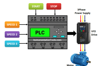
Proximity sensors are often used in machine vibration monitoring to measure the variation in distance between a shaft and its support bearing. Basically it is relative vibration measurement.

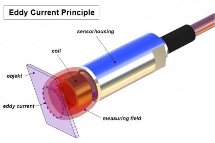
This is common in large critical machines like steam turbines, compressors, and motors that use sleeve-type bearings. The voltage is sent from the power supply through the oscillator demodulator to the probe tip. The distance from the probe tip to the shaft determines how much of this supplied voltage is returned back to the monitor through the extension cable and oscillator demodulator. It is usually a 3 wire circuit.

There is only one distance associated with any given voltage.

The aim of this article is to showcase the use of the proximity sensors beyond the relative vibration measurement, which is to determine the lifting of the shaft.

A jacking oil (and pump) is used on rotor shafts of the Turbine/compressor to provide even cooling of the shaft and eliminate rotor distortion caused by sags due to weight and bows due to uneven cooling. It is essential to measure whether a shaft is evenly jacked up by oil prior to the start-up of critical rotary equipment like a turbine/compressor.

This can be achieved during the initial alignment of the rotor by the OEM engineer with the help of a micrometer pointer placed on the shaft. Once it is jacked up, the needle on the shaft will move and show the reading.

This article elaborates on another method to determine shaft jacked up or not and how much jacked up so that it helps OEM engineers to troubleshoot any disturbance in a critical machine. Sometimes it also helps to determine the oil flow through variable orifice installed in oil lines used for jacking purposes.

Say, for example, a machine is installed with Bentley Nevada proximity transducer system [3300 XL 8 mm], as per the catalog of this proximity sensor, the sensitivity of the probe is 7.87 V/mm or 200 mV/mil (it is understood that proximity probe is installed within the distance specified in the catalog).

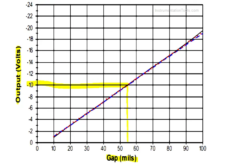
The below graph is available in the catalog, which shows the sensor linear range. Suppose proximity probes are set at -10V output, it means that the gap between sensor and shaft is ~55 mils. This is reading prior to jacking.

Vibration Sensor Linear Range

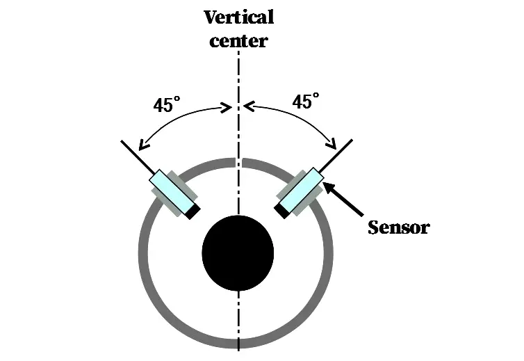
The actual installation of proximity probes will be as per the below figure. i.e. sensor (proximity probes) are placed at a 45-degree angle with respect to the horizontal and vertical centerline.

Installation of Proximitor

When the Jacking oil pump is started, and the shaft is lifted at that time, naturally, the gap between the probe and shaft will reduce. This is what we want to measure! Suppose after jacking, proximity reading went to -8 VDC.

So 2VDC is reduced, which means that (7.87 VDC-> 1 mm then 2VDC->mm?) 0.25 mm (~10 mils) Gap has been reduced between probe and shaft with respect to earlier. This is the way that proximity probe can be used as distance measurement as the shaft is not rotating, it is only lifted.

For illustration purposes, proximity reading before and after is attached to get better clarity. These reading also serves the records for future maintenance.

Determine Lifting of Shaft using Proximity Sensor

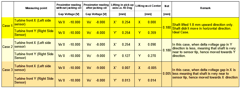
Now take the case 1 from the above proximity probe readings,

Using Pythagoras formula, (2Z)2 = X2 + Y2… when we have X=Y then Z =  [1 / √2 ] * X

X and Y can be known from Gap vs Voltage output.

For above example, Z = [1 / √2 ] * 10 = 7.07 mils (0.18 mm) has been jacked up due to jacking oil.

This can be rechecked with your field pointer dial reading. Once the proximity reading matches the field reading, this will reduce the time for the OEM engineer when he finds improper jacking.

Although proximity sensors are used for various diagnostic analysis, for rotary equipment this proximity sensor reading helps calculating the actual jacking during initial installation and related maintenance & troubleshooting as this reading will serve as a base condition of shaft/rotor with respect to the casing.

Author: Jatin Katrodiya

Read Next:

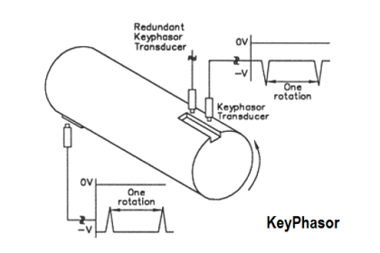
  • How Keyphasor works?
  • Vibration Probe Gap Voltage
  • What is TK-3 Calibrator?
  • Turbine Protective Devices
  • Turbine Supervisory Instrumentation
Don't Miss Our Updates
Be the first to get exclusive content straight to your email.
We promise not to spam you. You can unsubscribe at any time.
Invalid email address
You've successfully subscribed !

Continue Reading

Mechanical Vibration Switch Principle
Gap Voltage of Bently Nevada Vibration Probe
How to do calibration checks of vibration Probe, extension cable and vibration monitor
Accelerometer Vibration Probe Principle
Top 100 Vibration Analysis Questions and Answers
Vibration Probe Field Setting Procedure
Share This Article
Facebook Whatsapp Whatsapp LinkedIn Copy Link
Share
1 Comment
  • chintamani wamorkar says:
    April 7, 2023 at 12:05 pm

    Hi,

    Can you explain how you measured shaft lifting w.r.t center?

    Reply

Leave a Reply Cancel reply

Your email address will not be published. Required fields are marked *

Stay Connected

128.3kFollowersLike
69.1kFollowersFollow
210kSubscribersSubscribe
38kFollowersFollow

Categories

Explore More

Vibration Probe Commissioning Checklist
What is Keyphasor ? How does Keyphasor works ?
Vibration Monitoring System Step by Step Troubleshooting Guide
Non-contact Vibration Measurement
How Vibration sensors Work ?
What is TK-3 Calibrator ?
Vibration Switch Working Principle
Basics of Vibration Measurement

Keep Learning

Advantages and Disadvantages of Network Topology

Advantages & Disadvantages of Different Vibration Sensors

Turbine Supervisory Instrumentation

What is Turbine Supervisory Instrumentation (TSI)?

To check the characteristic of vibration probe

Bently Nevada Vibration Probes Functional Testing

Bently Nevada 3500 Machinery Protection Systems

Bently Nevada 3500 Machinery Protection Systems Hardware Modules

proximitor module

Bently Nevada Vibration System Verification Procedure

hall effect speed sensor

Speed Probe Working Principle

Bently Nevada Proximity Probe

Root Cause Analysis for Vibration Probe Not Responding

Seismic Transducers Objective Questions

Seismic Transducers Objective Questions

Learn More

Industrial Automation Controls used in HVAC

Industrial Automation Controls used in HVAC

PLC Control for Baking Machines Logic

PLC Programming for Baking with Auto and Manual Modes

General Specification of Thermowell

General Specification of Thermowell

Paddle Wheel Level Switch Principle

Paddle Wheel Level Switch Principle

Temperature Gauges and Elements Specifications

Temperature Gauges and Elements : Detailed Specifications

Instrument Air (IA) System

Process Design of Instrument Air System

Strain Gauge Bridge Circuit

Something is Wrong with Strain Gauge Bridge Circuit

Instrument Mechanic Interview Questions

Instrument Mechanic Interview Questions

Menu

  • About
  • Privacy Policy
  • Copyright

Quick Links

  • Learn PLC
  • Helping Hand
  • Part Time Job

YouTube Subscribe

Follow US
All rights reserved. Reproduction in whole or in part without written permission is prohibited.
Welcome Back!

Sign in to your account

Username or Email Address
Password

Lost your password?