Protective tripping systems provide a defence against excursions beyond the safe operating limits by detecting a excursions beyond set points related to the safe operating limits (i.e. the onset of a hazard) and taking timely action to maintain or restore the equipment under control to a safe state.
Trips should not be self resetting unless adequate justification has been made. Protective interlocks prevent those control actions which might initiate a hazard from being undertaken by an operator or process control system, and are by nature self-resetting.
Process Interlocks and Trips

Protection systems should indicate that a demand to perform a safety function has been made and that the necessary actions have been performed.
Independence
Protective systems should be sufficiently independent of the control system or other protective systems (electrical/electronic or programmable). Where there is an interface between systems (e.g. for indication, monitoring or shared components) or shared utilities (e.g. power), environment (e.g. accommodation, wiring routes) or management systems (maintenance procedures, personnel), then the method of achieving independence should be defined, and common cause failures adequately considered.
Measures to defend against common mode failures due to environmental interactions may include physical separation or segregation of system elements (sensors, wiring, logic, actuators or utilities) of different protective systems.
Independence will also be required for protection against systematic and common mode faults. Measures may include use of diverse technology for different protective systems. Where more than one E/E/PES protective system is used to provide the required risk reduction for a safety function, then adequate independence should be achieved by diverse technology, construction, manufacturer or software as necessary to achieve the requires safety integrity level.
Dependence on utilities
The action required from the protective system depend upon the nature of the process. The actions may be passive in nature, such as simple isolation of plant or removal of power, or they may be active in that continued or positive action is required to maintain or restore a safe state, for example by injection of inhibitor into the process, or provision of emergency cooling.
Active protective measures have a high dependence upon utilities, and may be particularly vulnerable to common mode failures. The scope of the protective system therefore includes all utilities upon which it depends, and they should have an integrity consistent and contributory to that of the remainder of the system.
Measures taken to defend against common mode failure of utilities will be commensurate with the level of safety integrity required, but may include standby or uninterruptable/reservoir supplies for electricity, air, cooling water, or other utilities essential for performance of the safety function. Such measures should themselves be of sufficient integrity.
Survivability and external influences
The protective system should be adequately protected against environmental influences, the effects of the hazard against which it is protecting, and other hazards which may be present.
Environmental influences include power system failure or characteristics, lightning, electromagnetic radiation (EMR) (IEC 61000), flammable atmospheres, corrosive or humid atmospheres, ingress of water or dust, temperature, rodent attack, chemical attack, vibration physical impact, and other plant hazards.
Degradation of protection against environmental influences during maintenance and testing should have been considered and appropriate measures taken. e.g. Use of radios by maintenance personnel may be prohibited during testing of a protective system with the cabinet door open where the cabinet provides protection against EMR.
Protection against random hardware faults
The architecture of the protective system should be designed to protect against random hardware failure. It should be demonstrated that the required reliability has been achieved commensurate with the require integrity level.
Defensive measures may include high reliability elements, automatic diagnostic features to reveal faults, and redundancy of elements (e.g. 2 out of 3 voting for sensors) to provide fault tolerance.
Protection common mode failures
Diversity of elements is not effective for protection against random hardware faults, but is useful in defence against common mode failures within a protective system.
Protection systematic failures
Protection against systematic hardware and software failures may be achieved by appropriate safety lifecycles.
Sensors
Sensors include their connection to the process, both of which should be adequately reliable. A measure of their reliability is used in confirming the integrity level of the protective system. This measure should take into account the proportion of failures of the sensor and its process connection which are failures to danger.
Dangerous failures can be minimised by a number of measures such as:
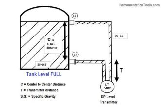
- Use of measurement which is as direct as possible, (e.g. pneumercators provide an inferred level measurement but actually measure back pressure against a head and are sensitive to changes in density due to temperature variations within the process, and to balance gas flow, upon which they are dependant);
- Control of isolation or bleed valves to prevent uncoupling from the process between proof tests or monitoring such that their operation causes a trip;
- Use of good engineering practice and well proven techniques for process connections and sample lines to prevent blockage, hydraulic locking, sensing delays etc.;
- Better Use of analogue devices (transmitters) rather than digital (switches);
- Use of positively actuated switches operating in a positive mode together with idle current (de-energise to trip);
- Appropriate measures to protect against the effects of the process on the process connection or sensor, such as vibration, corrosion, and erosion;
- Monitoring of protective system process variable measurement (PV) and comparison against the equivalent control system PV either by the operator or the control system.
Proof testing procedures should clearly set out how sensors are reinstated and how such reinstatement is verified after proof testing.
Maintenance procedures should define how sensors/transmitters are calibrated with traceability back to national reference standards by use of calibrated test equipment.
Other matters which will need to have been considered are:
- Cross sensitivities of analysers to other fluids which might be present in the process;
- Reliability of sampling systems;
- Protection against systematic failures on programmable sensors/analysers. The measures taken will depend on the level of variability and track record of the software. ‘Smart’ transmitters with limited variability software which are extensively proven in use may require no additional measures other than those related to control of operation, maintenance, and modification, whereas bespoke software for an on-line analyser may require a defence in depth against systematic failures (IEC 61508 Part 3);
- Signal conditioning (e.g. filtering) and which may affect the sensor response times;
- Degradation of measurement signals (distance between sensor and transmitter may be important);
- Accuracy, repeatability, hysteresis and common mode effects (e.g. effects of gauge pressure or temperature on differential pressure measurement);
- Integrity of process connections and sensors for containment (sample or impulse lines, instrument pockets are often a weak link in process containment measures).
Use of ‘SMART’ instruments requires adequate diagnostic coverage and fault tolerance (see architectural constraints in IEC 61508 Part 2), and measures to protect against systematic failures (software design/integration, inadvertent re-ranging during maintenance).
Measures may include use of equipment in non-smart mode (analogue signal output, no remote setting) and equipment of stable design for which there is an extensive record of reliability under similar circumstances.
Actuators and signal conversion
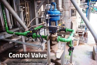
Actuators are the final control elements or systems and include contactors and the electrical apparatus under control, valves (control and isolation), including pilots valves, valve actuators and positioners, power supplies and utilities which are required for the actuator to perform its safety function, all of which should be adequately reliable.
A measure of their reliability is used in confirming the integrity level of the protective system. This measure should take into account the proportion of failures of the actuator under the relevant process conditions which are failures to danger.
Actuators are frequently the most unreliable part of the tripping process.
Dangerous failures can be minimised by a number of measures such as:
- Use of ‘fail-safe’ principles so that the actuator takes up the tripped state on loss of signal or power (electricity, air etc.). e.g. held open, spring return actuator;
- Provision of uninterruptable or reservoir supplies of sufficient capacity for essential power;
- Failure detection and performance monitoring (end of travel switches, time to operate, brake performance, shaft speed, torque etc.) during operation;
- Actuator exercising or partial stroke shutoff simulation during normal operation to reveal failures or degradation in performance. Note this is not proof testing but may reduce probability of failure by improved diagnostic coverage (IEC 61508);
- Overrating of equipment.
Other matters which should have been considered are:
- Valves should be properly selected for their duty, and it should not be assumed that a control valve can satisfactorily perform isolation functions;
- Actuators may also include programmable control elements (e.g. SMART instruments) particularly within positioners and variable speed drives and motor control centres. Modern motor control centres may use programmable digital addressing. This introduces a significant risk of introduction of systematic failure and failure modes which cannot be readily predicted. Such an arrangement should be treated with caution. It is normally reasonably practicable for trip signal to act directly upon the final contactor;
- Potential for failure due to hydraulic locking between valves (e.g. trace heated lines between redundant shutoff valves).
Logic systems
Commonly, the logic systems for protective systems are electronic, but programmable and other technology systems (magnetic or fluidic/pneumatic) have been used.
The architecture of the logic system will be determined by the hardware fault tolerance requirements, for example dual redundant channels. Where a high level of integrity for the system is required (SIL3 or SIL4) then diverse hardware between channels may be employed. This should not be confused with diversity of independent protective systems.
Logic systems are likely to incorporate provisions for fault alarms and overrides, for which there should be suitable management control arrangements. They may also provide monitoring of input and output signal lines for detection of wiring (open circuit, short circuit) and sensors/actuators (stuck-at, out of range). Such monitoring may initiate an alarm, a trip action or, in a voting arrangement, disable the faulty element.
Software based systems should be adequately protected against systematic failures, for example by an appropriate hardware and software safety lifecycles, and suitable techniques and quality systems. Guidance is available in IEC 61508 Part 3.
Wiring and communications (signal transmission)
Transmitters, communications devices and wiring systems should be arranged to meet the requirements for survivability, protection against external influences and independence.
Independent systems or redundant channels should not share multicore cables with each other or power circuits, and may require diverse routes depending upon the safety integrity level to be achieved.
Measures to protect against failures include:
- Use of fail-safe principles such as DC model (e.g. 4-20 ma loop) for analogue signal transmission diagnosis and alarm of out of range, abnormal, or fault states (such as stuck-at) with defined control system responses for both the sensor and transmitter;
- Cable selection (screening etc.);
- Protection of cables against fire, chemical attack, physical damage etc.;
- Physical separation or segregation of cables and cable routes;
- Routing in benign environments;
- Use of optical fibres to protect against electrical interference;
- Careful attention to lightning protection of data links between buildings.
Use of fieldbus or other digital communication protocols in protective systems should be considered a novel approach requiring a thorough evaluation and demonstration of the safety integrity.
Utilities
Utilities which are required for the protective system to perform its safety function may include power supplies such as electricity, air, inhibitor materials and their propellants, inert gas such as nitrogen, cooling water, steam, pilot flames and their gases all of which should be adequately reliable.
Measures such as redundancy, and uninterruptable/reservoir supplies, and availability monitoring (e.g. loss of air alarm) may be required. Confirmation that the designed capacity of reserves is adequate should be demonstrated by test.
Utilities may also introduce external influences into the protective systems (e.g. from electrical supplies) .
Measures to protect against external influences may include:
- Under/Over voltage protection;
- Overcurrent and short circuit protection;
- Use of an uninterruptable power supply or voltage conditioning or filtering;
- Careful attention to lightning protection and equipotential bonding.
Proof testing
The probability of failure on demand, or the failure rate of a protective system is critically dependent upon the frequency of proof testing and its ability to detect previously unrevealed failures of the system. The proof test interval should therefore be established accordingly, and as a rule of thumb for low demand systems, should be an order of magnitude less than the mean time between failure of the system and the demand rate.
Proof test procedures should be available which specify the success/failure criteria and detail how the test will be performed safely, including any management arrangements, operating restrictions and competence of personnel.
The tests should be arranged to reveal all dangerous failures which have been unrevealed in normal operation including the following measures:
- Tests performed at the conditions which would be expected at trip. (Where test under trip conditions cannot be performed, for example for safety reasons, then measures to ensure that potential failures at trip conditions will be revealed should be clarified);
- End to end tests at appropriate intervals, including proving sample/impulse lines. (Different elements of the protective system may require proof testing at different intervals).
Operation
Procedures should be available which detail the operation of the protective system including:
- Override management (authorisation, security, recording, monitoring and review of overrides, reset requirements);
- Operating instruction for trips;
- Instructions for response to equipment faults including fault alarms. (There should be procedural arrangements in place to ensure timely repair so that mean time to repair criteria can be met).
Maintenance
Procedures should be available for maintenance activities including:
- Maintenance instructions;
- Control of spares (segregation of faulty or non-conforming parts, identification to prevent interchange of similar parts etc.);
- Competence of maintenance personnel;
- Operating restriction during maintenance;
- Control of software back-ups and memory media (E/EPROMS, floppy disks, files on hard disks on portable PCs etc.);
- Post maintenance reinstatement and proof testing.
For systems where a high diagnostic coverage is claimed, for example high integrity high systems, the probability of failure (expressed as failure rate) is critically dependant upon the mean time to repair the faults revealed. For such systems, the repair performance should monitored and reviewed against the design criteria.
Modification
A management system for control of modifications should be available to ensure that:
- Unauthorised modifications are prevented;
- Authorised modifications are not ill conceived;
- Safety verification to confirm that the required safety function and integrity have been maintained;
- Designed and implementation is carried out by competent persons.
Remote diagnostic systems
Remote diagnostic systems have the potential to cause danger by initiating unexpected operations or by affecting safety functions by software/parameter modification or by diverting the control system processor from time critical functions.
The need for remote diagnosis should be justified, a risk assessment completed, and measures taken to ensure that safety is not affected by normal operation or malfunction of the diagnostic system, including the remote diagnostic terminal and software, communication link, and the control system diagnostic interface and software.
Consideration should be given to:
- Security and control of access;
- Communication between diagnostician and plant personnel;
- Restricted mode of operation; passive (monitoring only), active (control/operator functions), interactive (software change possible);
- Potential for operation outside restricted mode under fault conditions;
- Protection of safety functions from unauthorised modification;
- Change control;
- Competence of personnel.
Whilst beyond the scope of HS(G)87 ‘Safety in the remote diagnosis of manufacturing plant and equipment’, the publication provides a useful background to the subject.
Note : Contains public sector information licensed under Open Government Licence v3.0.
If you liked this article, then please subscribe to our YouTube Channel for PLC and SCADA video tutorials.
You can also follow us on Facebook and Twitter to receive daily updates.
Read Next:
What is Instrumentation Control System ?
Setpoints and Alarms in Control System
Raw Counts to Engineering Units
Difference Between SCADA and HMI





Alarms are used to alert operators of serious, and potentially hazardous, deviations in process conditions.
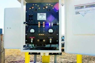
Key instruments are fitted with switches and relays to operate audible and visual alarms on the control panels and annunciator panels. Where delay, or lack of response, by the operator is likely to lead to the rapid development of a hazardous situation, the instrument would be fitted with a trip system to take action automatically to avert the hazard; such as shutting down pumps, closing valves, operating emergency systems.
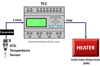
The basic components of an automatic trip system are:
1. A sensor to monitor the control variable and provide an output signal when a preset value is exceeded (the instrument).
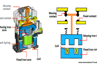
2. A link to transfer the signal to the actuator, usually consisting of a system of pneumatic or electric relays.
3. An actuator to carry out the required action; close or open a valve, switch off a motor.
Interlocks :
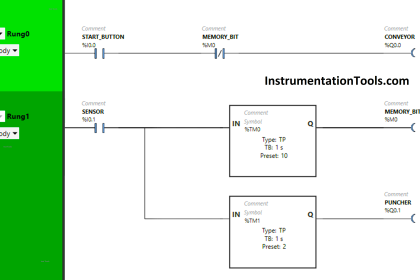
Where it is necessary to follow a fixed sequence of operations for example, during a plant start-up and shut-down, or in batch operations interlocks are included to prevent operators departing from the required sequence. They may be incorporated in the control system design, as pneumatic or electric relays, or may be mechanical interlocks. Various proprietary special lock and key systems are available.