Industrial Process Plant Projects are the result of activities and produced documentation by a group of different technical and non-technical teams, among which the Process Engineering Team is the main core of such group.
The activities and documentation of this team will specify the scope of roles and responsibilities of other teams of the mentioned group, and we try to explain the general overview of their roles and responsibilities inside Detail Design Engineering Company (Figure-1).
Process Engineering Roles & Responsibilities
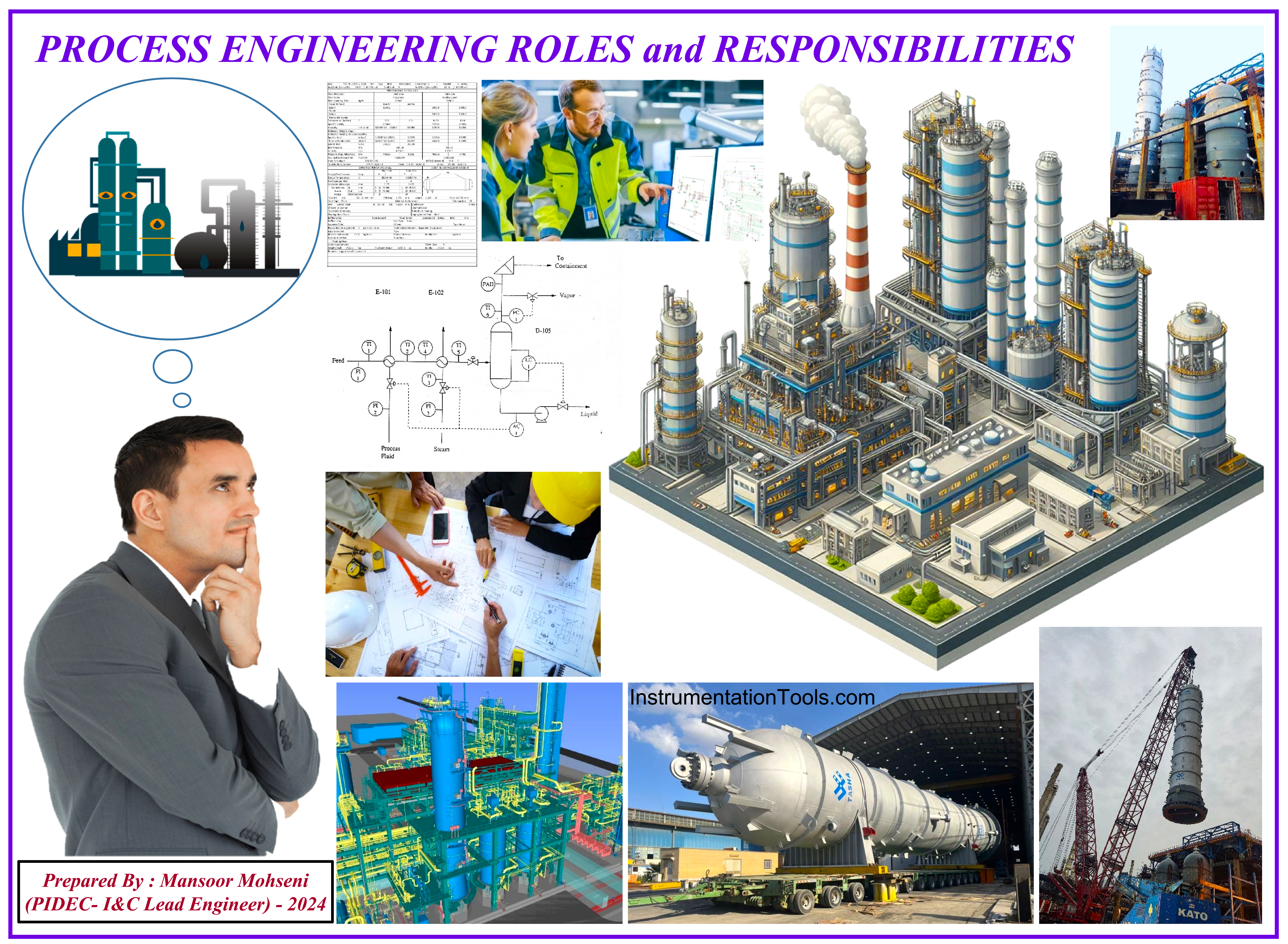
Figure 1: General Overview of Process Engineering Roles and Responsibilities.
Process Plant Project usually is defined as a type of project, in which the target of the project is making a plant/ factory in the field of chemical, oil & gas, petrochemical, and similar processes, in which Chemical Engineering is the core specifier for the concept of basics. Since different subjects of chemical engineering are used in such projects, the responsible team is assigned as PROCESS ENGINEERING Team or in the abbreviated form PROCESS-Team.
Activity Model of the Industrial Process Plant Project
Figure 2 is a typical graphical representation of the Process Plant Activity Model of the Industrial Process Plant Project. As Figure 2 shows the PROCESS (PR-Team) has main roles in different phases of the Industrial Process Plant Project (i.e. phases: Feed/ Basic Design, Detail Engineering Design, Construction/ Commissioning, and Operation).
As it is clear from Figure-2 detailed engineering Design may be considered as the most important phase of the Industrial Process Plant Project which has essential effects on the final performance and safety of the plant/ factory.
In fact, at this phase, the provided data and information (in Basic Phase) will be used for producing detail documents and purchasing required equipment, devices, and materials for the construction/installation/commissioning of the plant and then the required functionality and safety of the plant during the operation phase. Hence we focus on the Detail Engineering Phase in this article.
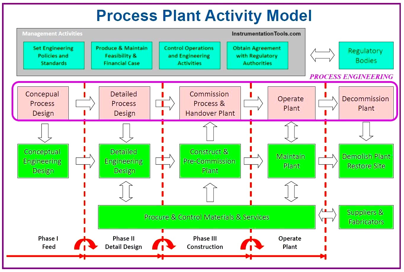
Figure-2: Industrial Process Plant Project Activity Model
Process Engineer Roles in Detail Design Engineering
Figure 3 shows a general overview of PROCESS-Team roles in the Detail Design/ Engineering of process plant project. Of course, coordination of PROCESS-TEAM with other technical teams will be done by producing documentation, common study, and review, meetings, discussion and negotiations, correspondences, site surveys…
As it is clear from the figure, the PROCESS-Team receives the project inputs (including Basic Design Package, Functional Requirements, Client Specifications, Design Codes, and Standards, …) , and then by considering Business Requirements and using Company Practices will do the required activities and produce the relevant documentations.
Such activities and documentation will provide input data and information for the other technical teams (including: I&C, PIPING, EL, CIVIL, MECHANIC, ROTARY EQUIPMENT …).
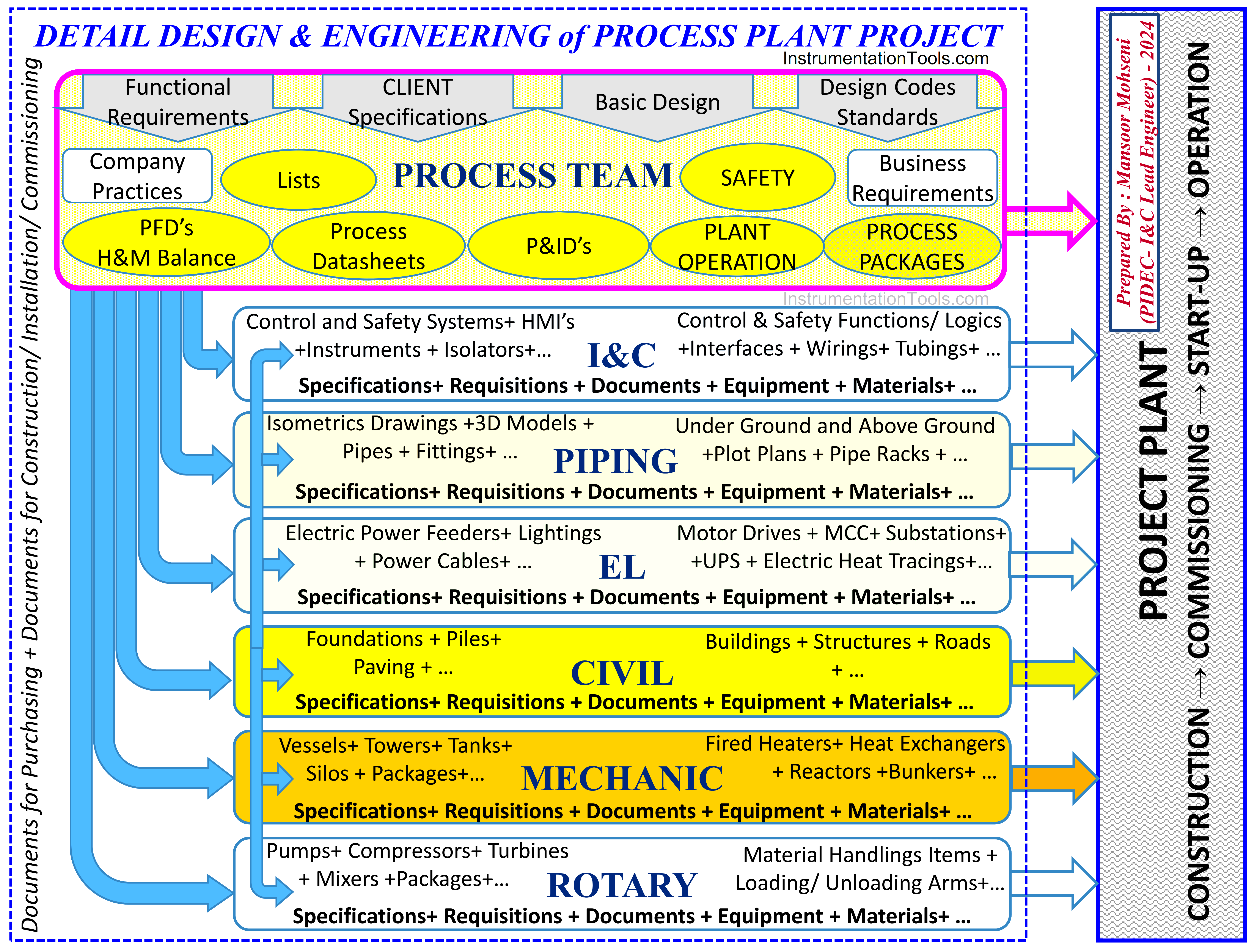
Figure-3: PR-TEAM Roles in Detail Design/ Engineering of Process Plant Project
Process team Main Activities & Documentation
PROCESS-TEAM during the Detail Design Engineering phase will do several activities and produce different documents in some main general approaches/ subjects (or titles) and are explained briefly.
Providing BFD and PFD
By such diagrams, PROCESS-TEAM explains the general overview of project plant requirements by using block symbols or shape symbol representations. Such documents may be provided as one overview sheet for the whole plant or may be provided by some sheets for different process units.
These documents are provided first as primary drawings for use in process simulation and doing required calculations, and then issued as complementary or final issues. Figures 4 and 5 show some samples of such documents.
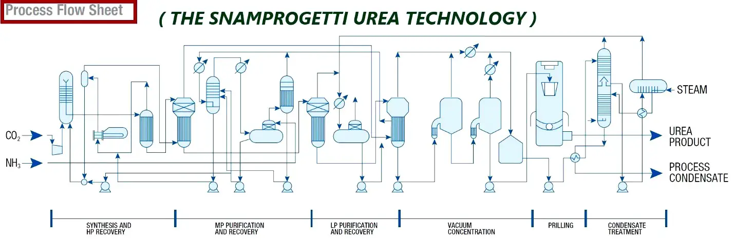
Figure-4: Samples of PROCESS FLOW SHEET and PROCESS BLOCK FLOW DIAGRAM which are provided by PR-TEAM.
BFD and PFD documents are used to introduce the all process units and main equipment of the project by a glance, and schematically show the mainstream and flow of materials and auxiliary utilities. These documents will be used as the basis for producing Piping and Instrumentation Diagrams or P&IDs.
P&ID drawings may be also considered as the abbreviation of Process & Interlock Diagram by some companies or agencies since it will be used to define process functions in view of the required instrumentations, systems, and interlocks.
However BFD and PFD documents are very good references for providing general overview sheets in HMI GRAPHIC DISPLAYS which are provided by the DCS System Vendor.
Figure-5: Two Samples of (a set of) PROCESS FLOW DIAGRAM which are provided by PR-TEAM for different process units of a process plant.
Process Simulation and Calculations
How to process the inlet fluid(s) to produce the required products(s), i.e., the Process, will be defined by performing Process Simulation.
These simulations use thermodynamic models to simulate fluid behaviors under the different process operations: phase separation, compression, heat exchange, expansion, etc.
Figure-6: Sample of PROCESS SIMULATION SOFTWARE which are usually used by PR-TEAM.
The software also calculates the duty of the equipment. For instance, the software will calculate the required capacity of the compressor to bring gas of such composition from a given inlet pressure to a given discharge pressure. The software incorporates thermodynamic models, which include the properties of all these components, and calculates the difference in enthalpy between the compressed and non-compressed gas, hence the required compressor capacity.
Such mechanical duty will in turn determine the size of the driver (gas or steam turbine for instance) by applying typical compressor efficiency, losses in gearbox, etc.
Running process simulations will allow us to try several scenarios and optimize the process, i.e., reduce the number of equipment, energy consumption, etc.
Process simulations are run for all operating cases, and so this determines the required capacity of each equipment. Minimum and maximum duties are identified covering the full range of operating cases. The range of operating conditions for each line (pressure, temperature, flow) is also identified, which will allow adequate line specification and sizing.
The results are tabulated in the heat and material balance document, which shows the flow, composition, and condition of each stream.
Developing P&ID’s
(This section is prepared via some extraction from : Piping and Instrumentation Diagram Development book, First Edition. Moe Toghraei. © 2019 John Wiley & Sons, Inc. Published 2019 by John Wiley & Sons, Inc. Companion website: www.wiley.com/go/Toghraei_PID)
P&ID is a type of engineering drawing that describes all the process steps of a process plant (See Figure-7).
The piping and instrumentation diagram (P&ID) is what might be considered the bible of a chemical process plant (CPI). It provides a lot of information for the manufacturing of the equipment, installation, commissioning, start‐up, and the operation of a plant. It also presents how a process plant should handle emergency situations.
The P&ID is a frequently referenced document throughout a project term – from the designing stages to the plant‐in‐operation phase – by various engineering disciplines, in technical meetings with vendors or manufacturers, hazard and operability study (HAZOP) meetings, management meetings, and project scheduling and planning. It is also one of the few documents created by multiple engineering groups such as Process, Instrumentation and Control (I&C), Plot plant and Piping (PL&P), Mechanical, Heat Ventilation and Air Conditioning (HVAC), and to a lesser extent Civil, Structural, and Architecture (CSA) and environmental or regulatory groups.
Based upon the Basic Design Process P&ID’s, Engineering Contractor (Company) shall develop and prepare detail design P&ID’s for each Process Unit to be approved for design and then follow through to approve for construction incorporating vendors’ information.
The information provided by the P&ID allows for the generation of other documents, including piping isometric drawings, the piping model, equipment and instrument lists, cause‐and‐effect diagrams, control philosophy, alarm set‐point tables, line designation table (LDT) or line list, material take‐offs, loop diagrams, tie‐in lists, and many more. The P&ID can ironically be considered an acronym for “primary inter-disciplinary document.”
The I&C Team has a very close relation with the PROCESS-Team to develop and finalize the P&ID documents, especially for specifying instruments, assigning tag numbers, and finalizing required functionalities in Process Control and Safety Systems, further to logics and interlocks and operator facilities (HMI’s).
The Piping group should be familiar with P&ID because it is their main working document and they need this to develop their piping model and piping isometric drawings. Civil engineers should also know P&IDs, although to a lesser extent. However, if the materials are concrete, like in large wastewater treatment plants, they should be familiar with P&IDs.
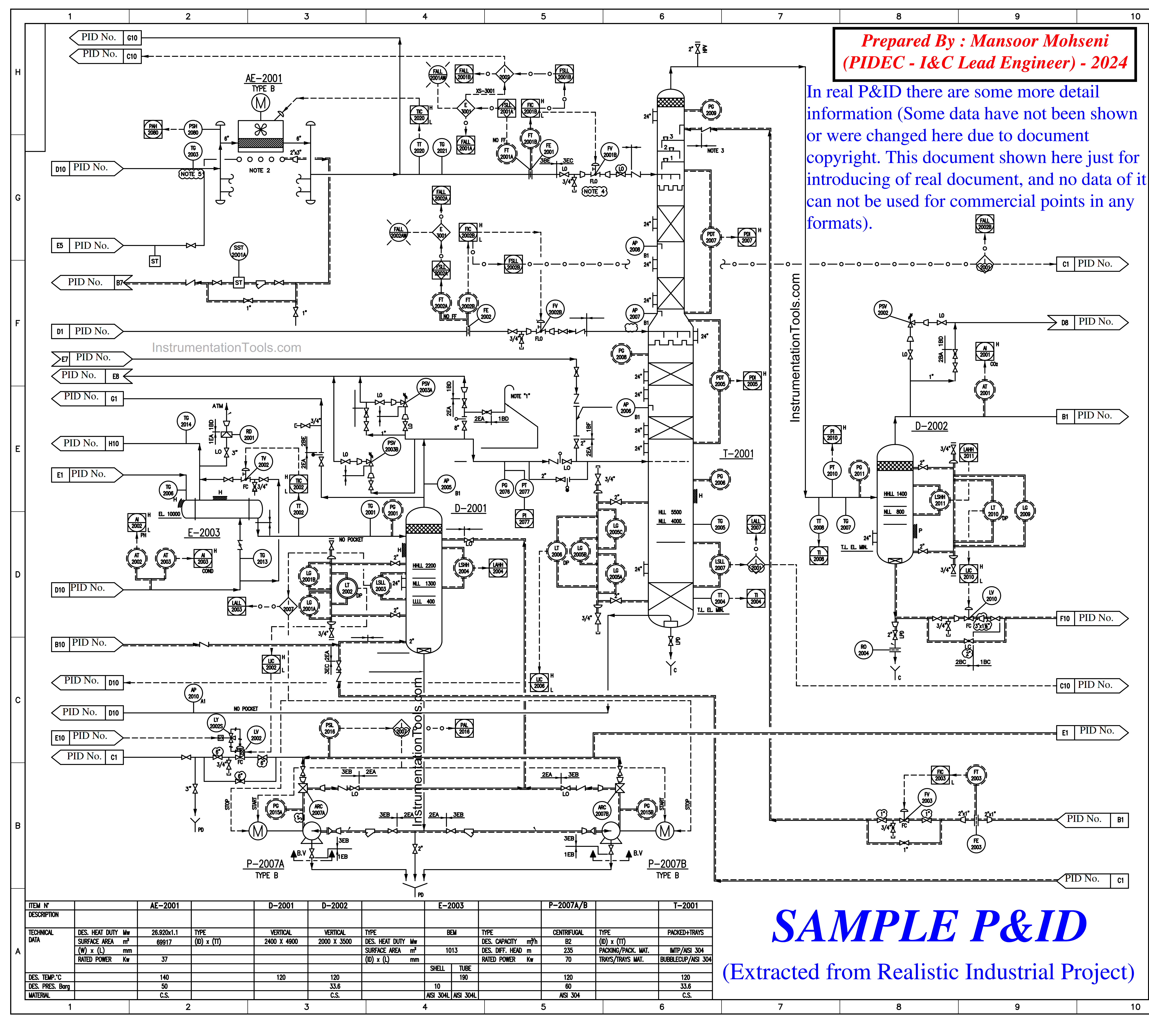
Figure-7: Sample of P&ID which shall be prepared and developed by PR-TEAM.
However, it should be mentioned that in HAZOP meetings, the discussion is mainly on P&IDs and about different potential hazards in a designed plant and the required safeguards.
The P&ID shall show the interfaces with other drawings including but not limited to those supplied parts by the vendor (equipment and packages). In case any P&ID is prepared by vendors, the said P&IDs should comply with the Process Plant P&ID requirements.
The P&ID documents usually are prepared in four parts (or category types): General (including Legend sheets), Process, Utility, and Auxiliary/ Offsite/ Battery Limits.
Process Datasheets
(This section is prepared via some extraction from: Detailed Design Engineering and Procurement (Project Standard and Specification)-Rev 07 document –Feb 2011, Issued by KLM Technology Group-Malaysia (karl@kolmetz.com))
PROCESS-Team shall study and investigate the process plant conditions and after Process Simulation shall provide all required data which shall be reflected in Data Sheet Documents such as Ambient & Site Condition (Figure-8), Utility Data (Figure-9), Equipment Datasheet (Figure-10), Specialty Item Datasheets (if any), and all required process data to be reflected in Package Requisitions (datasheets) or Instrument (and Valve) Datasheets and also Pressure Safety Valve Datasheets.
Ambient & Site Condition
The ambient and Site Condition document further shows the basis of Process Design will help other technical disciplines (especially the I&C Team) in considering environmental conditions for their equipment and devices (instruments).
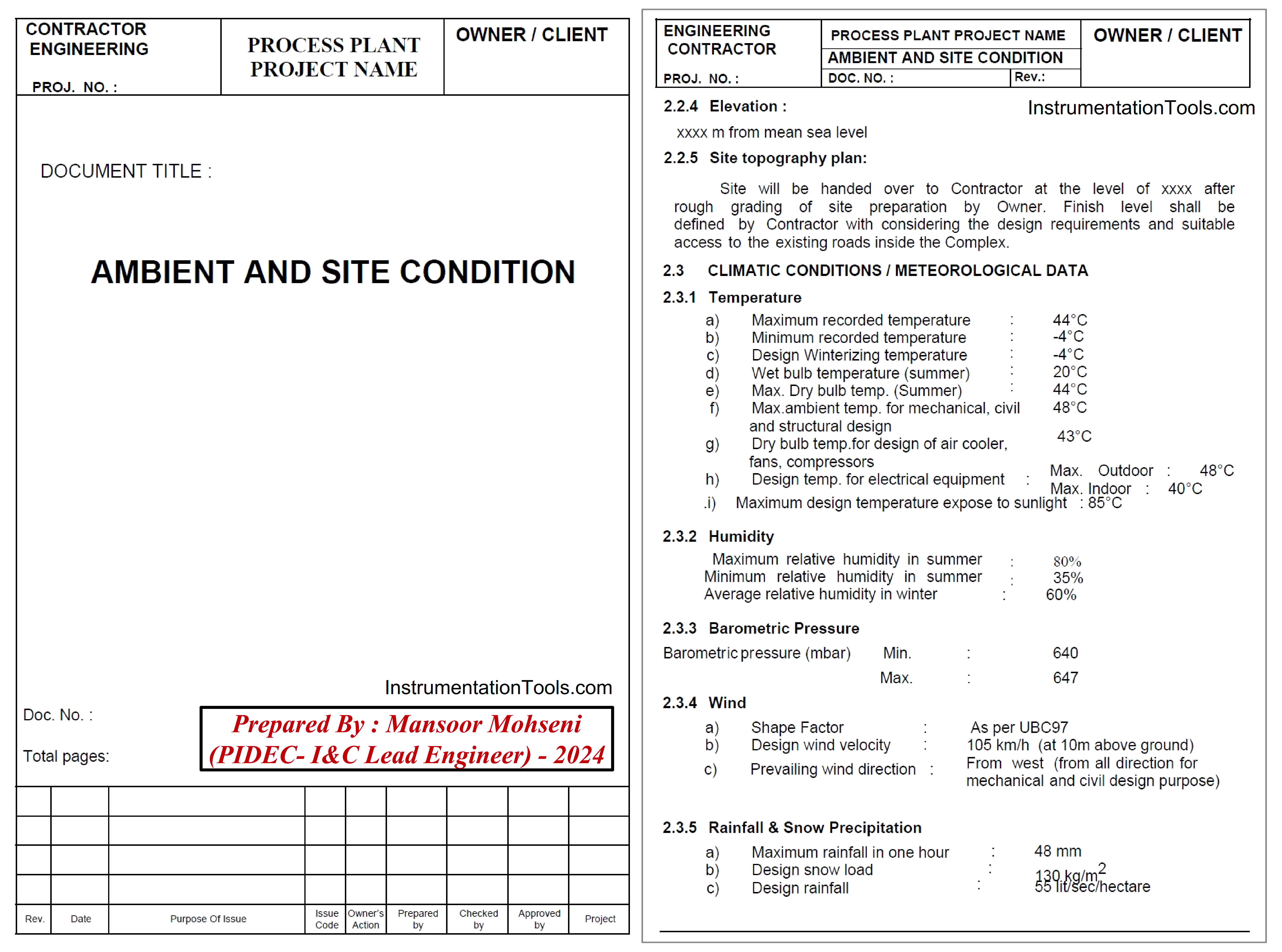
Figure-8: Sample of Ambient & Site Condition document which shall be prepared by PR-TEAM.
Utility Data
Utility Datasheet (Figure-9) provides the conditions and requirements of the utilities used in the process plant as complete utility summary tables like:
- Electricity Power System (different available AC and DC Voltage Feeders)
- Steam System (all types including HHPS, HPS, MPS, LPS)
- Condensate (all types)
- Boiler Feed Water (BFW)
- Cooling Water (all types), Demineralized Water, Fire Water, Desalinated Water, Potable Water, Plant/ Service Water, Polished Water,…
- Air System (Instrument Air and Plant Air)
- Nitrogen
- Fuels (Gas and Oil)
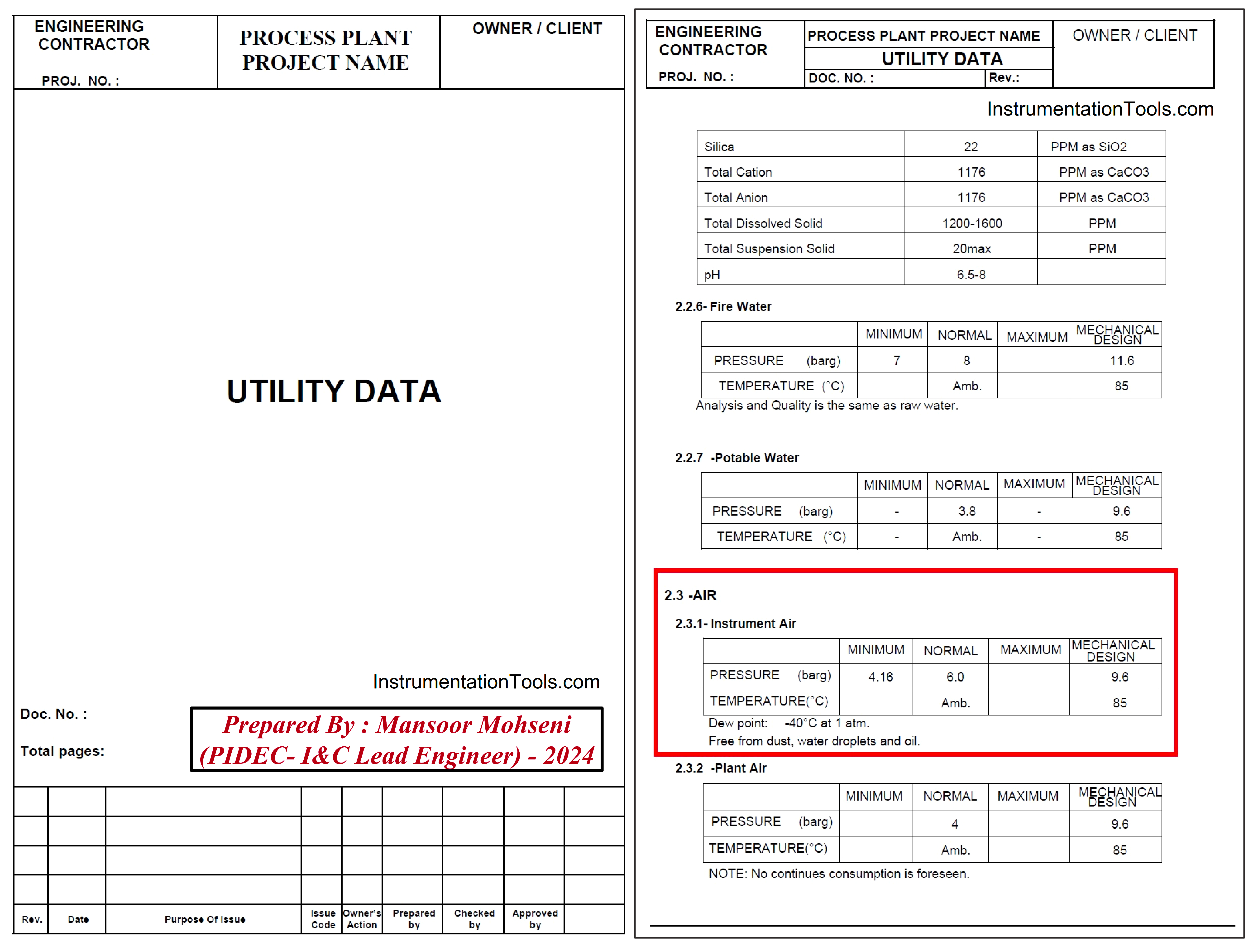
Figure-9: Sample of Utility Data document which shall be prepared by PR-TEAM.
Further to the Utility Datasheet Document, PROCESS-Team shall prepare a Utility Distribution P&I Diagram too, for each Process Unit showing distribution of the all utility services as mentioned above.
All headers, branches to the users, and all miscellaneous items such as utility stations, safety showers, eye washes and etc. with full detail shall also be shown ( Note: in some companies mentioned safety items may be followed by Safety or HSE Team).
Equipment Data
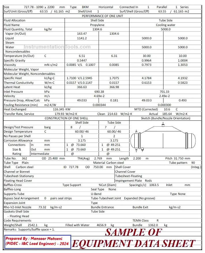
Figure-10: Sample of Equipment Datasheet document which shall be filled for Process Data by PR-TEAM.
PROCESS-Team based on the results of found process data, then shall perform the sizing of equipment as per the required process duty, e.g., the size of the gas compressor according to the required gas flow and gas gravity, the size of the cooling water pump as per process fluid cooling requirements and calorific value, etc. and Site conditions, e.g., the temperature of available cooling medium (air/ sea water).
Hydraulic Design
PROCESS-Team also shall perform complete hydraulic design (calculations) at rated (design) capacity and at the end limit values of defined turndowns and mechanical stress resistance (i.e. Lower Operating Levels and Maximum Possible Pressures/ Flows/ Levels) for each part of the Process Units within the Units Battery Limits.
Hydraulic Design shall include, but not be limited to the following:
- Calculation of Line Sizes
- Control valve process design specifications (e.g., differential pressure across the control valve, etc.).
- Pump suction and discharge pressure and NPSH.
- Equipment elevations
- Compressor inlet/ discharge pressure.
- Equipment and piping design pressures.
- Liquid flows in towers and vessels to ensure satisfactory hydraulic flows.
- Relief systems including relief valve specifications.
- Equipment to be purchased, to ensure that such equipment will perform satisfactorily within the system for which it is specified.
On the other hand, PROCESS-Team based on the above-mentioned studies and calculations shall complete process information on all equipment data sheets including instruments, vessels, heat exchangers, heaters, electrical motors, fans and blowers, and all other miscellaneous equipment or packages required for the process plant project.
List
PROCESS-Team shall provide some documents as list formats due to a summary of their studies and calculations on process plant projects like Line List (Figure-11) and Process Equipment List (Figure-12), Alarm Set-Point List, Process Fluid List, Utility Consumption Lit, Process Fluid List, …
Some of the mentioned required lists in the Process Plant Project may be merged or inserted in other documents by the PROCESS Team (based on Detail Design Engineering Company practice/ procedure). As an example Utility Consumption List may be inserted in the Utility Data document.
Further to the mentioned lists, the PROCESS Team shall help other technical disciplines with the preparation of their list format documents too. As an example, the PROCESS Team helps the electrical team with the preparation of the Electrical Load (and Motor) List document or Motor Feeder Types List (which clarifies the functionality and required interfaces of each motor ).
Figure-11: Sample of Line List document which is provided by PR-TEAM.
Figure-12: Sample of Equipment List document which is provided by PR-TEAM.
Interactions of PROCESS Team with Other Technical Teams
As Figure-3 shows, PROCESS Team has huge interactions with other technical disciplines which are done by producing documents and data or via the mentioned coordination. Figure 13 shows some of the main roles (activities and data/ documents) that are in the PR-Team scope of work for developing the Plot Plan Document(s) by the PIPING-Team.
Figure-13: General Information Required for Developing Plot Plan and the main roles of PR-Team.
PROCESS-Team has close interactions with I&C-Team for implementation of required functionalities of Process Plant Projects by safety and Control Systems (such interactions will be explained in more detail in another article).
A summary of some PROCESS-Team interactions with other teams can be found in Figure-3. It shall be noticed that some interactions with other disciplines may be done by simultaneous effects of other disciplines too.
This figure also implicitly shows PROCESS-Team interaction with the Procurement Team for purchasing and supplying some process packages that are in PROCESS-Team scope (Note: such scope of supply may differ in different Detail Design Engineering Companies).
Safety activities of PROCESS Team
The safety concerns/ requirements of each Industrial Process Plant have close relation with its process functionality, and so the PROCESS-Team shall engage seriously in Safety activities and documentation (Note: in some Detail Design Engineering Companies, Safety activities and documentation are done directly by the PROCESS-Team or by some section of Process Department).
Due to the importance of considering Safety Requirements and close relations with PR-Team activities and documentation, such a subject will be explained in a separate article.
Summary
In this article, we have reviewed the main roles and responsibilities of PROCESS ENGINEERING TEAM (PR-TEAM).
However, the main documents and activities of the PROCESS Team can be listed below:
- Process Simulation
- Process Design Criteria
- Process Design Basis
- Block Flow Diagrams (BFD)
- Process Flow Diagrams (PFD)
- Heat and Material Balances
- Process Studies
- Process Calculations
- Piping & Instrumentation Diagrams (P&ID)
- Line Designation Tables / Line List
- Ambient & Site Condition Data
- Process Equipment List
- Utility Consumption List
- Process Fluids List
- Equipment Process Data Sheets
- Process Description & (Operating) Control Philosophy
- Emergency Shut-Down Diagrams
- Cause & Effects Diagrams
- Advanced Process Control Description / Diagram
- Specialty Item Data Sheets
- Standard Operating Procedures (SOP) / Operating Manual
- Pressure Safety Valves Data Sheets Relief Load Summary
- Heat Exchanger Thermal Datasheet…
References:
- Safety Roles & responsibilities of Process Engineering
- I&C and Process Teams Interactions (in Detail Design Engineering)
- I&C Engineer Roles & Responsibilities – Instrumentation Design
- Instrumentation Engineer Activities & Documents – Detail Design Phase