A relief valve or pressure relief valve (PRV) is a type of safety valve used to control or limit the pressure in a system; pressure might otherwise build up and create a process upset, instrument or equipment failure, or fire.
The pressure is relieved by allowing the pressurized fluid to flow from an auxiliary passage out of the system. The relief valve is designed or set to open at a predetermined set pressure to protect pressure vessels and other equipment from being subjected to pressures that exceed their design limits.
When the set pressure is exceeded, the relief valve becomes the “path of least resistance” as the valve is forced open and a portion of the fluid is diverted through the auxiliary route.
The diverted fluid (liquid, gas or liquid–gas mixture) is usually routed through a piping system known as a flare header or relief header to a central, elevated gas flare where it is usually burned and the resulting combustion gases are released to the atmosphere.
As the fluid is diverted, the pressure inside the vessel will stop rising. Once it reaches the valve’s re-seating pressure, the valve will close. The blowdown is usually stated as a percentage of set pressure and refers to how much the pressure needs to drop before the valve reseats.
The blowdown can vary from roughly 2–20%, and some valves have adjustable blowdowns.
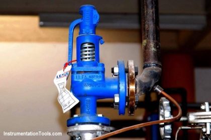
Pressure Relief Valve

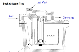
Relief Valve Parts :
- Inlet Nozzle,
- Valve Seat,
- Seat Holder,
- Valve Body,
- Set Pressure Adjusting Screw,
- Cap,
- Spring,
- Bonnet,
- Seal
In high-pressure gas systems, it is recommended that the outlet of the relief valve is in the open air. In systems where the outlet is connected to piping, the opening of a relief valve will give a pressure build up in the piping system downstream of the relief valve. This often means that the relief valve will not re-seat once the set pressure is reached.
For these systems often so called “differential” relief valves are used. This means that the pressure is only working on an area that is much smaller than the openings area of the valve. If the valve is opened the pressure has to decrease enormously before the valve closes and also the outlet pressure of the valve can easily keep the valve open.
Another consideration is that if other relief valves are connected to the outlet pipe system, they may open as the pressure in exhaust pipe system increases. This may cause undesired operation.
In some cases, a so-called bypass valve acts as a relief valve by being used to return all or part of the fluid discharged by a pump or gas compressor back to either a storage reservoir or the inlet of the pump or gas compressor. This is done to protect the pump or gas compressor and any associated equipment from excessive pressure.
The bypass valve and bypass path can be internal (an integral part of the pump or compressor) or external (installed as a component in the fluid path). Many fire engines have such relief valves to prevent the over-pressurization of fire hoses.
In other cases, equipment must be protected against being subjected to an internal vacuum (i.e., low pressure) that is lower than the equipment can withstand. In such cases, vacuum relief valves are used to open at a predetermined low pressure limit and to admit air or an inert gas into the equipment so as control the amount of vacuum.
Important Points :
The term relief valve is associated with the terms pressure relief valve (PRV), pressure safety valve (PSV) and safety valve:
Pressure relief valve (PRV) or Pressure Release valve (PRV) or pressure safety valve (PSV):
The difference is that PSVs have a manual lever to activate the valve in case of emergency. Most PRVs are spring operated. At lower pressures some use a diaphragm in place of a spring. The oldest PRV designs use a weight to seal the valve.
Set pressure:
When the system pressure increases to this value, the PRV opens. The accuracy of the set pressure may follow guidelines set by the American Society of Mechanical Engineers (ASME).
Relief valve (RV):
A valve used on a liquid service, which opens proportionally as the increasing pressure overcomes the spring pressure.
Safety valve (SV):
Used in gas service. Most SVs are full lift or snap acting, in that they pop completely open.
Safety relief valve (SRV):
A relief valve that can be used for gas or liquid service. However, the set pressure will usually only be accurate for one type of fluid at a time.
Pilot-operated relief valve (POSRV, PORV, POPRV):
A device that relieves by remote command from a pilot valve which is connected to the upstream system pressure.
Low-pressure safety valve (LPSV):
An automatic system that relieves by the static pressure of a gas. The relieving pressure is small and near the atmospheric pressure.
Vacuum pressure safety valve (VPSV):
An automatic system that relieves by the static pressure of a gas. The relieving pressure is small, negative and near the atmospheric pressure.
Low and vacuum pressure safety valve (LVPSV):
An automatic system that relieves by the static pressure of a gas. The relieving pressure is small, negative or positive, and near the atmospheric pressure.
Pressure vacuum release valve (PVRV):
A combination of a vacuum pressure and a relief valve in one housing. Used on storage tanks for liquids to prevent implosion or over pressure.
Snap acting:
The opposite of modulating, refers to a valve that “pops” open. It snaps into full lift in milliseconds. Usually accomplished with a skirt on the disc so that the fluid passing the seat suddenly affects a larger area and creates more lifting force.
Modulating:
Opens in proportion to the over-pressure.


Thanks for sharing it
is there any accuracy criteria for prv