Inst ToolsInst ToolsInst Tools
  • Ask
  • Courses
  • Videos
  • Q & A
    • Interview
      • Instrumentation
      • Electronics
      • Electrical
      • Practical Questions
    • MCQ
      • Instrumentation MCQ
      • Electrical MCQ
      • Electronics MCQ
      • Control Systems MCQ
      • Analog Electronics MCQ
      • Digital Electronics MCQ
      • Power Electronics MCQ
      • Microprocessor MCQ
      • Multiple Choice Questions
  • EE
    • Electronics
      • Electronics Q & A
      • Electronic Basics
      • Electronic Devices & Circuits
      • Electronics Animation
      • Digital Electronics
    • Electrical
      • Electrical Basics
      • Electrical Q & A
      • Power Electronics
      • Electrical Machines
      • Electrical Animation
      • Power Systems
      • Switchgear & Protection
      • Transmission & Distribution
  • Measure
    • Control Valves
    • Calibration
    • Temperature
    • Pressure
    • Flow
    • Level
    • Analyzers
    • Switches
    • Vibration
    • Solenoid Valve
  • Control
    • PLC Tutorials
    • Control Systems
    • Safety Instrumented System (SIS)
    • Communication
    • Fire & Gas System
  • More
    • Design
    • Tools
    • Animation
    • Basics
    • Formulas
    • Standards
    • TextBooks
    • Common
    • Software
    • Excel Tools
    • Erection & Commissioning
    • Process Fundamentals
    • Videos
    • Books
Search
All rights reserved. Reproduction in whole or in part without written permission is prohibited.
Reading: Pressure Control Loop Wiring Connections
Share
Notification Show More
Font ResizerAa
Inst ToolsInst Tools
Font ResizerAa
  • Courses
  • PLC Tutorials
  • Control Systems
Search
  • Ask
  • Courses
  • Videos
  • Q & A
    • Interview
    • MCQ
  • EE
    • Electronics
    • Electrical
  • Measure
    • Control Valves
    • Calibration
    • Temperature
    • Pressure
    • Flow
    • Level
    • Analyzers
    • Switches
    • Vibration
    • Solenoid Valve
  • Control
    • PLC Tutorials
    • Control Systems
    • Safety Instrumented System (SIS)
    • Communication
    • Fire & Gas System
  • More
    • Design
    • Tools
    • Animation
    • Basics
    • Formulas
    • Standards
    • TextBooks
    • Common
    • Software
    • Excel Tools
    • Erection & Commissioning
    • Process Fundamentals
    • Videos
    • Books
Follow US
All rights reserved. Reproduction in whole or in part without written permission is prohibited.
Inst Tools > Blog > Control Systems > Pressure Control Loop Wiring Connections

Pressure Control Loop Wiring Connections

Last updated: January 14, 2020 10:00 am
Editorial Staff
Control Systems
No Comments
Share
4 Min Read
SHARE

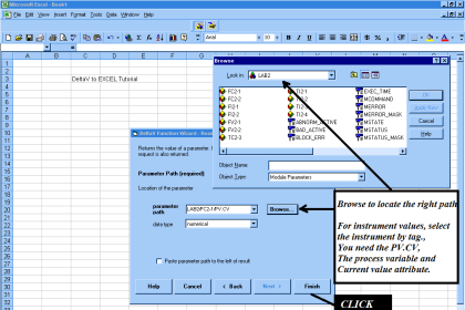
This pictorial diagram shows the wiring connections for a simple pressure control loop, where a loop- powered 4-20 mA pressure transmitter sends a signal to a Honeywell controller, which in turn sends another 4-20 mA signal to a control valve:

Contents
Pressure Control LoopSolution:Current Flow Direction in Pressure Control LoopRead Next:

Pressure Control Loop

Pressure Control Loop

Answer the following questions on the above shown pressure control loop.

Sketch all directions of current, using conventional flow notation.

Identify which electrical devices in this system act as sources and which act as loads.

If an operator informs you that the pressure indicated by the Honeywell controller is below range (“pegged” full downscale, reading −25%), what types and locations of electrical faults might you suspect? Are there any non-electrical faults which might also cause this to happen?

If an operator informs you that the control valve remains fully shut no matter the output value of the controller (even in “manual” mode), what types and locations of electrical faults might you suspect? Are there any non-electrical faults which might also cause this to happen?

Suppose that a short-circuit developed between the transmitter wires in the four-conductor cable. Explain what effect this would have on the operation of the system, as well as how you could determine that this fault was in the cable (and not in the transmitter) with your only piece of test equipment being a voltmeter.

Solution:

Even though the loop-powered transmitter does exert control over the amount of current sent to the controller’s input, the transmitter acts as a load rather than a source. In other words, it functions as a current regulator while relying on the 24 VDC power supply to be the source of motive power in the circuit.

Current Flow Direction in Pressure Control Loop

Pressure Control Loop Wiring Connections

A full-downscale (−25%) reading at the controller suggests a 0 volt signal at the controller’s input terminals. This could be caused by an open fault in the transmitter wiring somewhere, because this correlates with a zero current signal. It could also be caused by a short across the 250 ohm resistor. The fault must be electrical in nature, as no other kind of problem will cause the controller to lose all signal.

An unresponsive control valve suggests a lack of air pressure reaching its diaphragm. This may be caused by any kind of electrical fault in the output circuit (open or short) preventing current from reaching the I/P transducer. It might also be the consequence of an air supply failure, or perhaps a mechanical failure inside the I/P.

A short-circuit fault in the transmitter wiring will cause full current (> 20 mA) to be sent to the controller, making it “peg” full upscale. Normally, an ammeter would be a helpful tool to isolate the location of this fault, but here we only have access to a voltmeter.

In order to locate shorted faults using a voltmeter, we must break the circuit and then measure voltage “upstream” (toward the source) to see whether or not the shorted fault is “downstream” (toward the load).

Credits: Tony R. Kuphaldt

Read Next:

  • Live Zero in 4-20 mA Loop
  • Why we Tune a PID Controller?
  • 4-20 mA Formula
  • Compare Fieldbus & 4-20 mA
  • Control Loop Testing
Don't Miss Our Updates
Be the first to get exclusive content straight to your email.
We promise not to spam you. You can unsubscribe at any time.
Invalid email address
You've successfully subscribed !
Proportional-only Control Theory
Package System Architecture – Control & Instrumentation
14 Basic Control Systems Questions for Interview Preparation
Process Control & Safety Systems Logics Implementing Cycle
Basics of 4-20mA Current Loop
Share This Article
Facebook Whatsapp Whatsapp LinkedIn Copy Link
Share
Leave a Comment

Leave a Reply Cancel reply

Your email address will not be published. Required fields are marked *

Stay Connected

128.3kFollowersLike
69.1kFollowersFollow
208kSubscribersSubscribe
38kFollowersFollow

Categories

Recent Comments

  • Guifty Shimica on Top Non-PLC Certification Courses for Automation Professionals
  • Guifty Shimica on Top Non-PLC Certification Courses for Automation Professionals
  • MIHARITSOA Aina Sitraka on Top Non-PLC Certification Courses for Automation Professionals
  • Vaishnavi on Free Instrumentation Course for Trainee Engineers

Related Articles

Single Loop Control

Cascade Control Principle

Most Common Types of Cyber Attacks

20 Most Common Types of Cyber Attacks

Chart Recorders

What is a Recorder ?

Pre-commissioning or Commissioning Activities

Pre-commissioning or Commissioning Activities

What is Instrumentation and Control

What is Instrumentation and Control ?

Automation in Mining Industry

Industrial Automation in the Mining Industry

Manufacturing Execution System in Industrial Automation

Manufacturing Execution System (MES) in Industrial Automation

BPCS Control System and ESD Safety System of Delta-V DCS

BPCS Control System and ESD Safety System of Delta-V DCS

More Articles

Digital Electronics MCQ

Quine McCluskey Logic Functions Objective Questions

IR Instrumentation Questions & Answers

IR Instrumentation Questions & Answers

Venturi Flow Meter

Venturi Flow Meter – Working Principle, Advantages, Animation

Troubleshooting a Biased Transistor

Troubleshooting a Biased Transistor

What is Gas Chromatography

What is Gas Chromatography?

CNC Machining Glass Industry

5 Ways CNC Machining is Benefiting the Glass Industry

Classification of HVAC chillers

Classification of HVAC Chillers

Globe Valve Disk and Stem Connections

Globe Valve Seat and Disk

Follow US
All rights reserved. Reproduction in whole or in part without written permission is prohibited.
Welcome Back!

Sign in to your account

Username or Email Address
Password

Lost your password?