Inst ToolsInst ToolsInst Tools
  • Courses
  • Automation
    • PLC
    • Control System
    • Safety System
    • Communication
    • Fire & Gas System
  • Instrumentation
    • Design
    • Pressure
    • Temperature
    • Flow
    • Level
    • Vibration
    • Analyzer
    • Control Valve
    • Switch
    • Calibration
    • Erection & Commissioning
  • Interview
    • Instrumentation
    • Electrical
    • Electronics
    • Practical
  • Q&A
    • Instrumentation
    • Control System
    • Electrical
    • Electronics
    • Analog Electronics
    • Digital Electronics
    • Power Electronics
    • Microprocessor
Search
  • Books
  • Software
  • Projects
  • Process
  • Tools
  • Basics
  • Formula
  • Power Plant
  • Root Cause Analysis
  • Electrical Basics
  • Animation
  • Standards
  • 4-20 mA Course
  • Siemens PLC Course
Reading: Power Factor Controller (PFC) – Commissioning
Share
Notification Show More
Font ResizerAa
Inst ToolsInst Tools
Font ResizerAa
  • Courses
  • Design
  • PLC
  • Interview
  • Control System
Search
  • Courses
  • Automation
    • PLC
    • Control System
    • Safety System
    • Communication
    • Fire & Gas System
  • Instrumentation
    • Design
    • Pressure
    • Temperature
    • Flow
    • Level
    • Vibration
    • Analyzer
    • Control Valve
    • Switch
    • Calibration
    • Erection & Commissioning
  • Interview
    • Instrumentation
    • Electrical
    • Electronics
    • Practical
  • Q&A
    • Instrumentation
    • Control System
    • Electrical
    • Electronics
    • Analog Electronics
    • Digital Electronics
    • Power Electronics
    • Microprocessor
Follow US
All rights reserved. Reproduction in whole or in part without written permission is prohibited.
Inst Tools > Blog > Control Systems > Power Factor Controller (PFC) – Commissioning

Power Factor Controller (PFC) – Commissioning

Capacitors in most power factor correction (PFC) equipment draw a current that leads the voltage, thus producing a leading power factor.

Last updated: September 28, 2022 2:23 pm
Hussien Ghareb
Control Systems
No Comments
Share
5 Min Read
SHARE

Today we are going to discuss very important devices called Power Factor correction controllers; what is the need of these devices and how it works that is we are going to speak about.

Contents
Power Factor Controller (PFC)How Does the Power Factor Controller Work?Electrical InstallationSteps for CommissioningSteps for Quick Commissioning

Our scope will be for the common VarPlus-Logic device that is represented by Schneider.

Power Factor Controller (PFC)

These types of devices are used to monitor the power consumption of your plant and by its role, it will regulate the steps of your capacitors (automatically) in order to enhance and improve the power factor in your plant.

With the efficient use of this device, the industry can improve the efficiency of the system by reducing losses and reduced apparent power demand charges.

How Does the Power Factor Controller Work?

The idea behind the power factor correction by the use of the Capacitors. The capacitors are connected in parallel with the Power-incoming network as shown in the next Figure.

power factor correction equipment

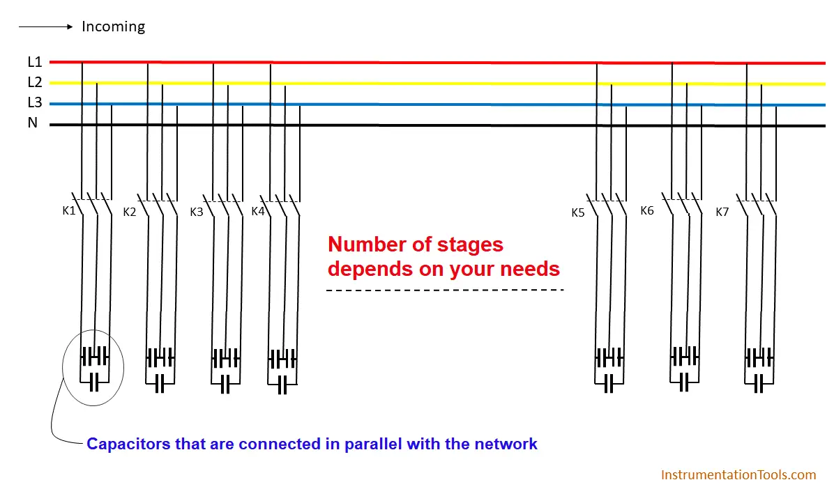
Capacitors contained in most power factor correction equipment draw a current that leads the voltage, thus producing a leading power factor.

If capacitors are connected to a circuit that operates at a nominally lagging power factor, the extent that the circuit lags is reduced proportionately.

Electrical Installation

The VarPlus controllers are able to control six stages (6L) or twelve stages (12L), which depends on your needs and your device version, the device can be connected to either 220V/400V AC that depends on your selection.

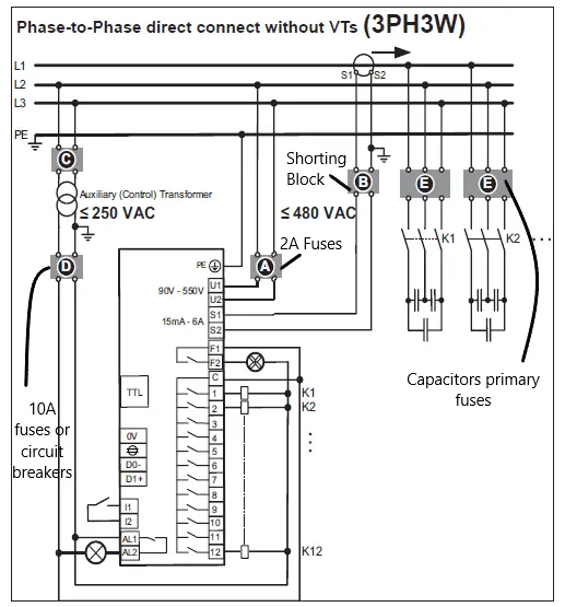
For the next figure, we can see it is a phase to phase connection (480 VAC) the two phases are connected to (U1 . U2).

power factor correction using capacitors

Note

In case of disconnecting the current transformer (CT) because of rewiring or panel maintenance, you have to ensure that the CT terminals are shorted, because an open circuited CT makes a huge amount of volt across the secondary winding, and that could make a series danger for the Technician that is dealing with.

Steps for Commissioning

This device has two modes for commissioning:

  • Quickstart menu (commonly used).
  • Advanced menu setup for this mode you have to enter each parameter of your device by yourself, which makes it a kind of complex in most situations.

Steps for Quick Commissioning

You can enter the quick start menu by selecting the 100 sub-menu from the PARAMETER menu.

  1. At first you need to enter the Ph-Ph voltage, the default value is 400V but you have to define the exact value of your station.
  2. Then the device asking for (CT) the current transformer factor that is written on the CT itself.
  3. If you are adjusting your device with the power network for the first time, you have to turn on the AUTO initializing that switches all outputs, during the test the controller determines the outputs that are working. It can also correct the voltage and current connections when the phases are swapped.
  4. Then you have to adjust the PFC power factor control parameter as following:

ON control is in Automatic mode.

OFF control stops and active steps will be disconnected.

Hold control stops and active steps remains in.

  • Here you can set the desired value of the power factor by adjusting CP1, the default value is 0.95 but you have the option to change it.
  • Finally, you have to set the time for the Switch Interval that is the time delay between switching steps in regulation.

Note

You will not find the setting of the cooling fan at the Quick start menu so, if you are using a cooling fan, you have to enter the desired temperature set point on parameter 511.

When the temperature drops under the set point the contact of the fan will be energized to turn the fan ON until it can achieve the set point again.

If you liked this article, then please subscribe to our YouTube Channel for Instrumentation, Electrical, PLC, and SCADA video tutorials.

You can also follow us on Facebook and Twitter to receive daily updates.

Read Next:

  • Identify PLC Critical Alerts
  • Monitor PLC Memory Usage
  • Instrument for Plausibility Checks
  • PLC Hard Stop Events from Faults
  • Assign Register Blocks by Function
Don't Miss Our Updates
Be the first to get exclusive content straight to your email.
We promise not to spam you. You can unsubscribe at any time.
Invalid email address
You've successfully subscribed !

Continue Reading

What is a Feedback Control System? Types & Advantages
PID Controller Functions
Liquid Level Control using Flow Loop
What is Interposing Relay in a PLC System ?
Instrumentation Cyber Security Glossary
How to Stop Cyber Attacks on PLC or DCS?
Share This Article
Facebook Whatsapp Whatsapp LinkedIn Copy Link
Share
Leave a Comment

Leave a Reply Cancel reply

Your email address will not be published. Required fields are marked *

Stay Connected

128.3kFollowersLike
69.1kFollowersFollow
208kSubscribersSubscribe
38kFollowersFollow

Categories

Explore More

Pressure Control Loop Wiring Connections
How to Select the Right Type of Controller
Chemical Reactor Temperature Control System
What is Instrument Hook Up Diagram ?
Basic Process Control System
Does Really a Safety Barrier is Important? – PLC DCS Systems
Learn about PLC, DCS, RTU, SCADA, and PAC
Understanding a Process Control Loop

Keep Learning

ICS Control System

ICS Control System Security

What is a Floating License - Automation Software Systems

What is a Floating License? – Automation Software Systems

Integral Control Principle

Integral Controller Principle

PID Controllers with output high select Logic

PID Controllers with Output High Select Logic

Emergency Stop Push button

Emergency Stop Switch Spurious Trip

PID-Controller-Simulator-graph

PID Controller Tunning Parameters Simulator

PID-Controller-Selection

PID Controller Selection

Python in Industrial Automation

Python in Industrial Automation and Control Systems

Learn More

Formula for Linear mA to Square root mA conversion

Temperature Transmitter Formula

Calculate Temperature Transmitter Output

Irrigation based Projects

Irrigation based Projects for College Students

Advanced Ladder Logic PLC Example

Automatic Sanitizer – Complex Ladder Logic PLC Examples

Pressure Gauges Common Problems

Pressure Gauges : Common Causes for Failures and Their Effective Solutions

Turbine Control System

Turbine Control System

Megger Circuit Diagram

Multimeter & Megger Principle

Bit Shift Registers PLC Program

PLC Light Sequence Control using Bit Shift Registers

Follow US
All rights reserved. Reproduction in whole or in part without written permission is prohibited.
Welcome Back!

Sign in to your account

Username or Email Address
Password

Lost your password?