The single-phase fully controlled rectifier allows the conversion of single-phase AC into DC. All four devices used are Thyristors.
Full-wave Rectifier With R and RL Load
The supplied firing signals determine the instants at which these devices switch on.
Turn-off happens when the current through the device reaches zero and it is reverse biased at least for a duration equal to the turn-off time of the device specified in the datasheet.
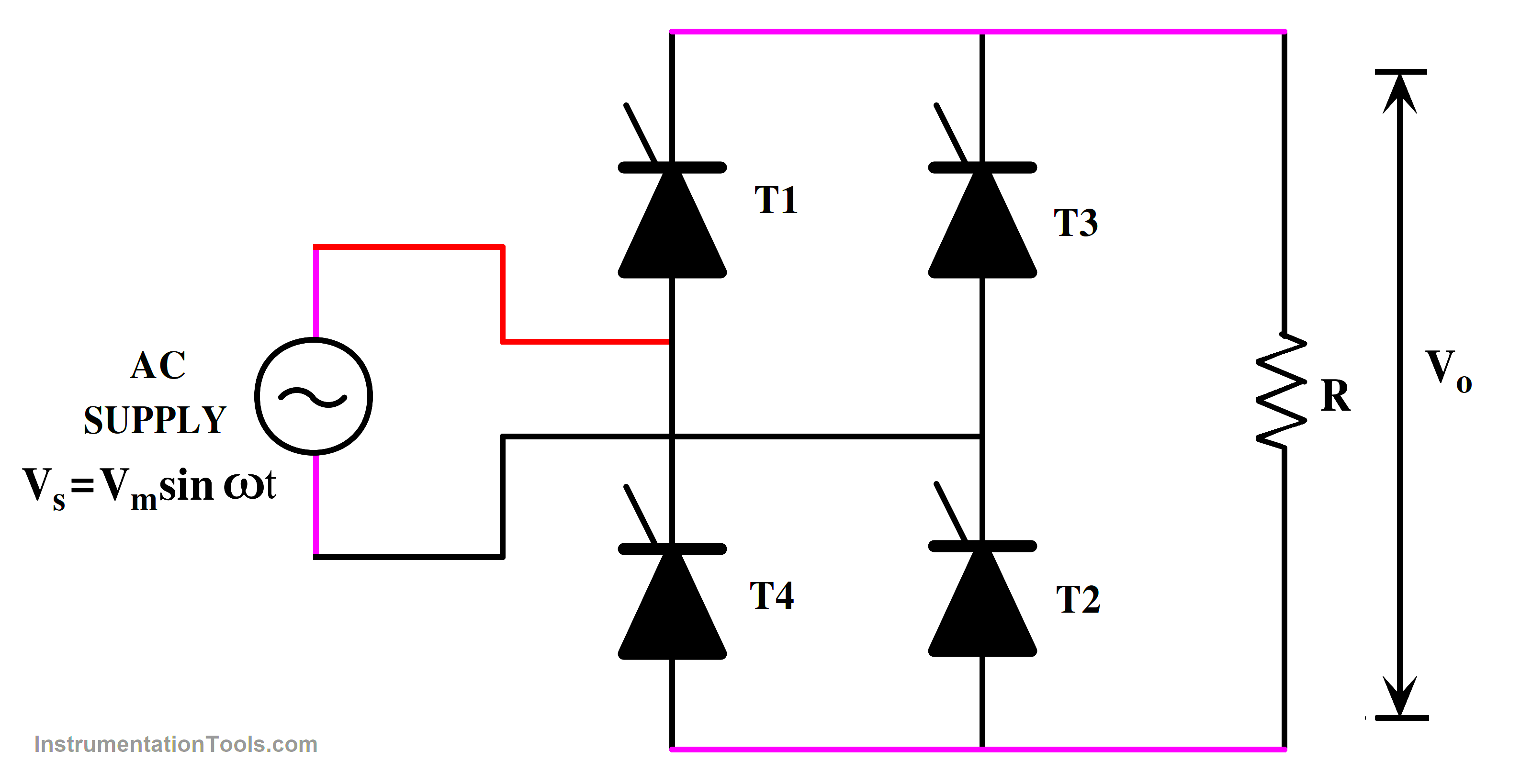
Fig 1. Single Phase Full-controlled Rectifier R Load
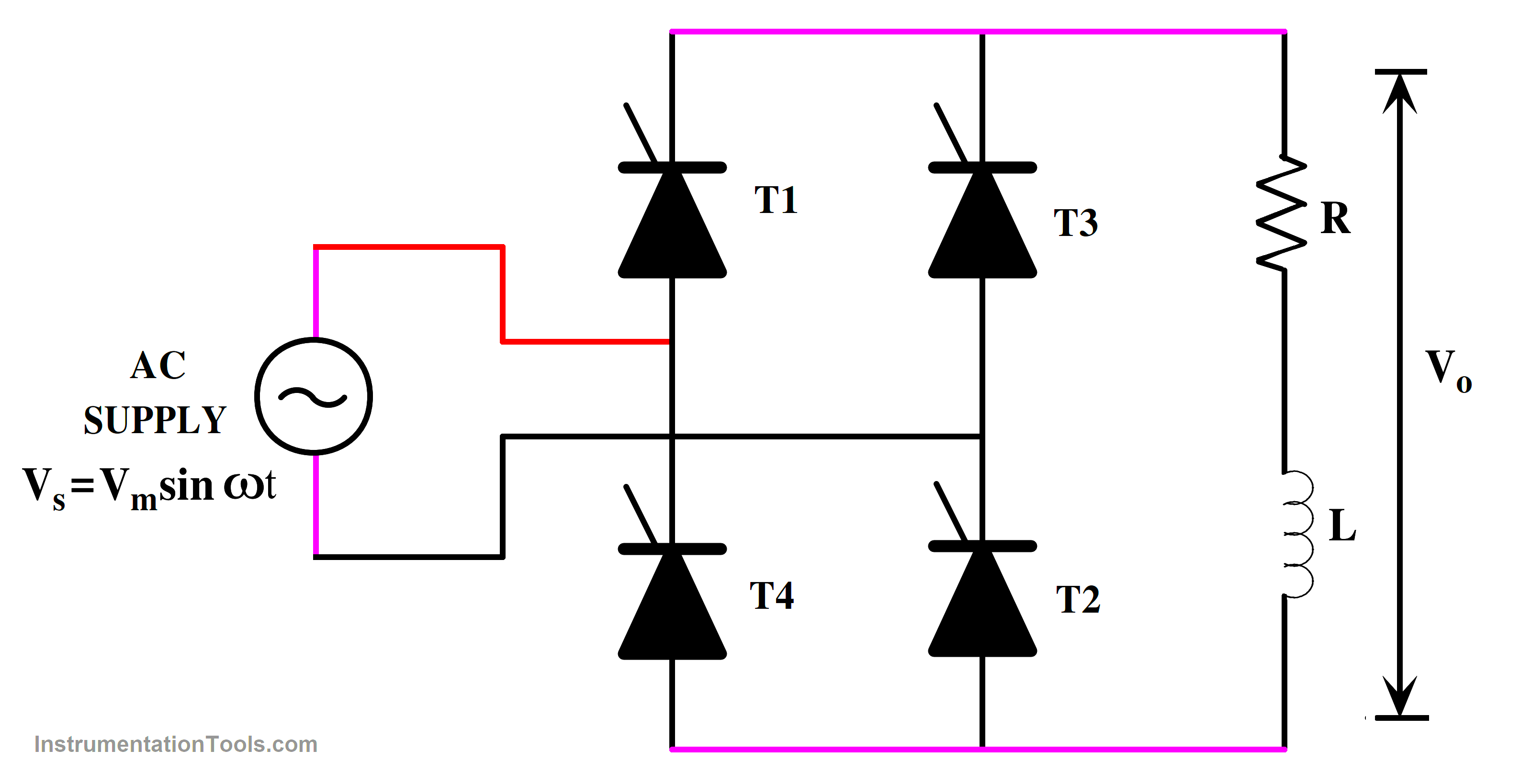
Fig 2. Single-phase Full-controlled Rectifier RL Load
Components of Single Phase Full Controlled Rectifier
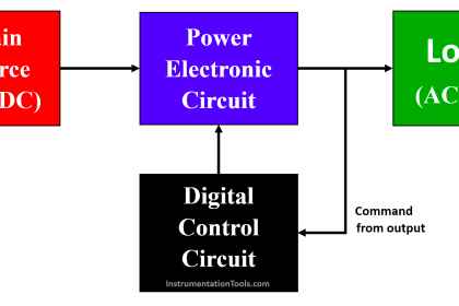
AC Power Supply: The input power source is typically an AC supply.
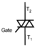
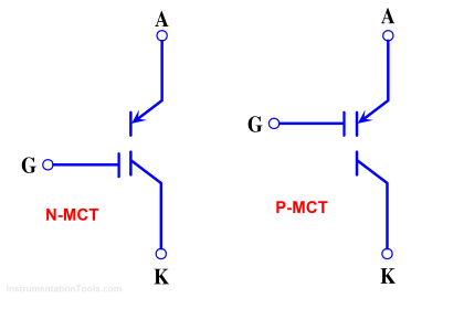
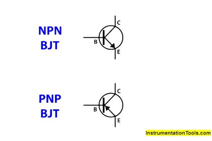
Thyristor(s) (SCR): Thyristors are semiconductors that act as controlled rectifiers. Since the above circuit is a bridge circuit. It consists of 4 thyristors.
The article consists of two circuits namely R load and RL load
- Resistive Load (R): A load with resistive in nature.
- Inductive Load (RL): A load with inductance, such as a motor or a transformer.
Resistor (R): A resistor may be connected in series with the inductive load to limit the current.
Single Phase Full Bridge Converter With R Load
a. Positive Half-Cycle
The thyristor is triggered into conduction at α (firing angle) during the positive half-cycle of the input AC voltage. The conductivity of the thyristor enables current to move through the load (R) and thyristor (T1 & T2) simultaneously.
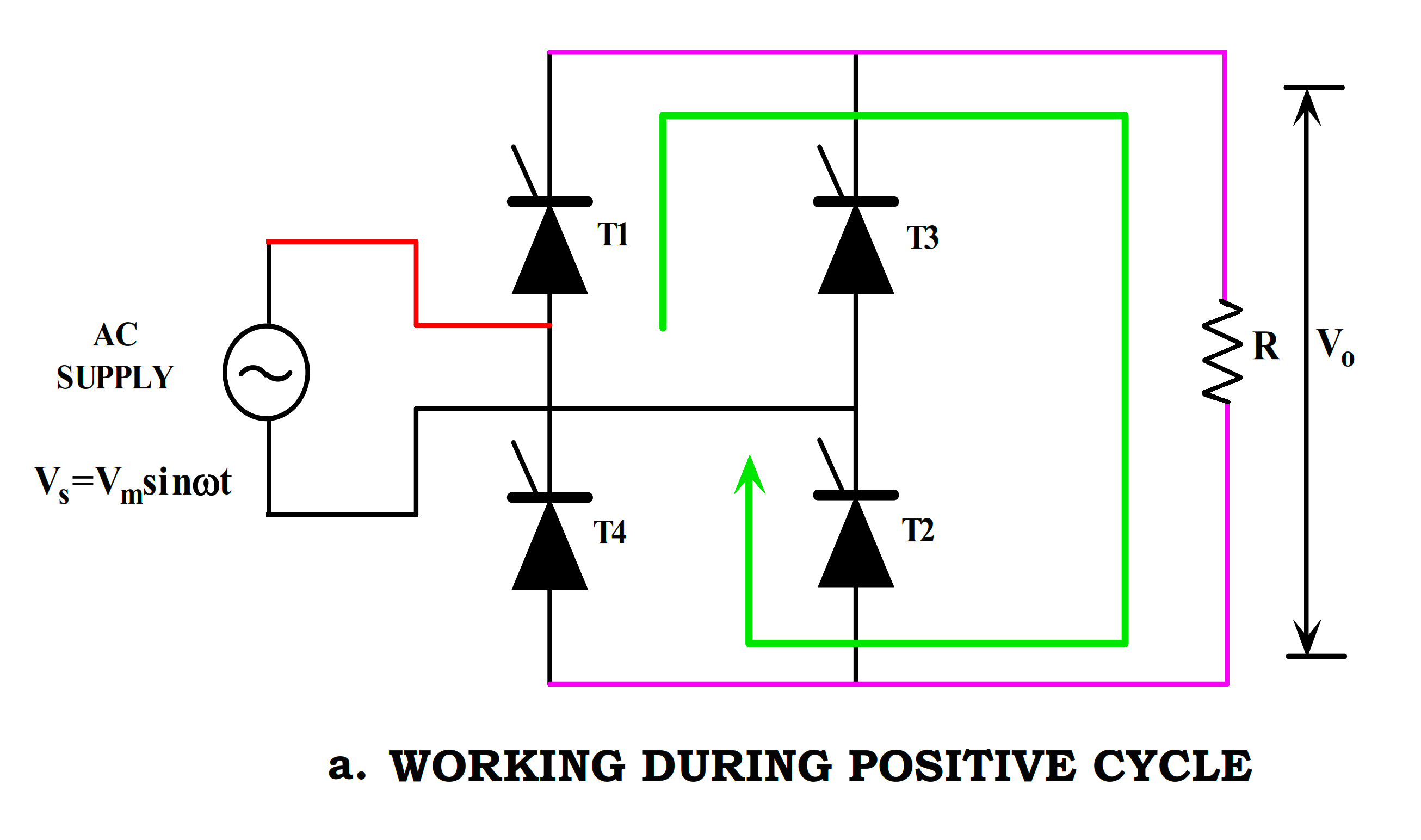
Fig 3.1 – Working of Full Converter During Positive Cycle
The input voltage changes polarity at the conclusion of the positive half-cycle, resulting in the thyristor’s natural shutdown.
b. Negative Half-Cycle:
The thyristor (T1&T2) is reverse-biased and does not conduct during the negative half-cycle of the input AC voltage. However, during this half-cycle, the thyristors (T3 & T4) conduct, and current flows through the load.
Both the output voltage and current are positive cycles in this setup. This is a result of the load being positive with regard to the ground throughout both cycles.
Similar to this, the thyristor (T3 & T4) is off during the positive cycle, and the input voltage changes polarity causing the thyristor to naturally turn off.
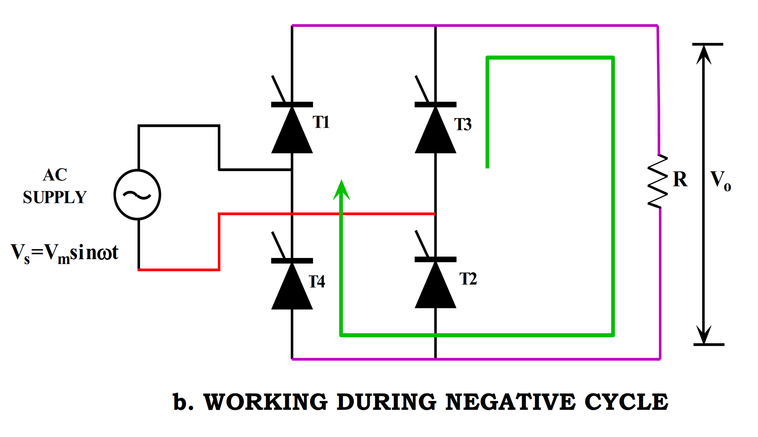
Fig 3.2 – Working of Full Converter During Negative Cycle
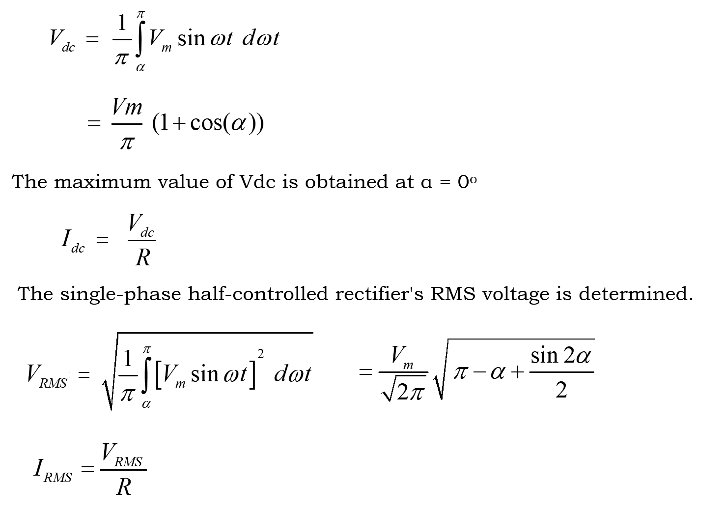
The single-phase full-wave circuit’s average voltage VO over load R is calculated as follows:
Single Phase Full Bridge Converter With RL Load
a. Positive Half-Cycle:
During the positive half-cycle of the input AC voltage, the thyristor (T1 & T2) is triggered at α (firing angle) into conduction. The thyristor conducts, allowing the current to flow through the inductive load (RL) and the thyristor. The load current rises, and energy is stored in the inductor.
At the end of the positive half-cycle, the input voltage reverses polarity, causing the thyristor (T1 & T2) to naturally turn off.
The inductive load tries to maintain the current flow after the thyristor turns off. However, since the thyristor is off, the load continuously conducts until the charges are present in the inductor. But the inductor discharges current in the reverse direction.
b. Negative Half-Cycle:
During the negative half-cycle of the input AC voltage, both the thyristor (T1 & T2) do not conduct. No current flows through the load during this half-cycle using T1 & T2.
Thyristor T3 & T4 conducts during the negative cycle. Similarly, the inductor stores the charges during the negative cycle.
At the end of the negative half-cycle, the input voltage reverses polarity, causing the thyristor (T3 & T4) to naturally turn off. However, the load continuously conducts until the charges are present in the inductor in the reverse direction.
The single-phase full-wave circuit’s average voltage V0 over load RL is calculated as follows:
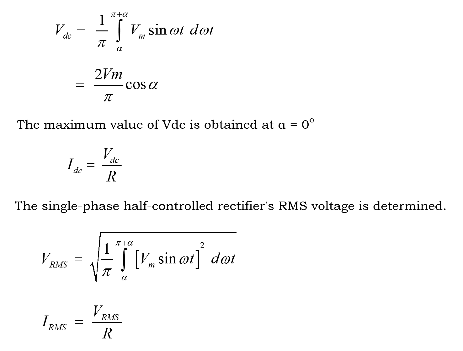
When α= 90°, the output voltage will be zero. It implies that there will be an equal amount of positive and negative areas in the output voltage, resulting in zero output voltage.
The converter functions in inversion mode for firing angles α greater than 90°. For α = 180, the voltage will be maximally negative.
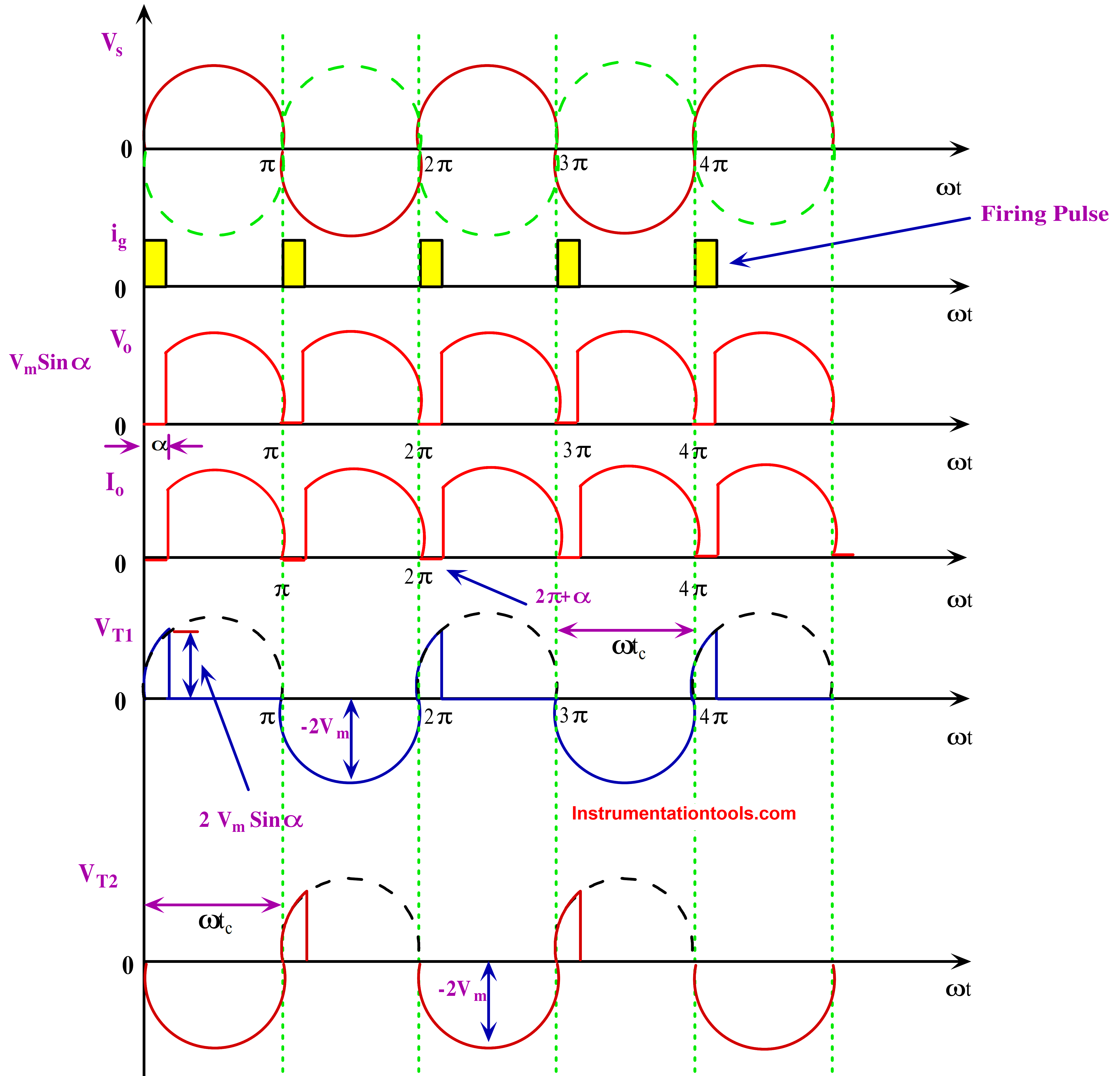
Fig 4.1 Full Controlled Rectifier With R Load Output Waveform
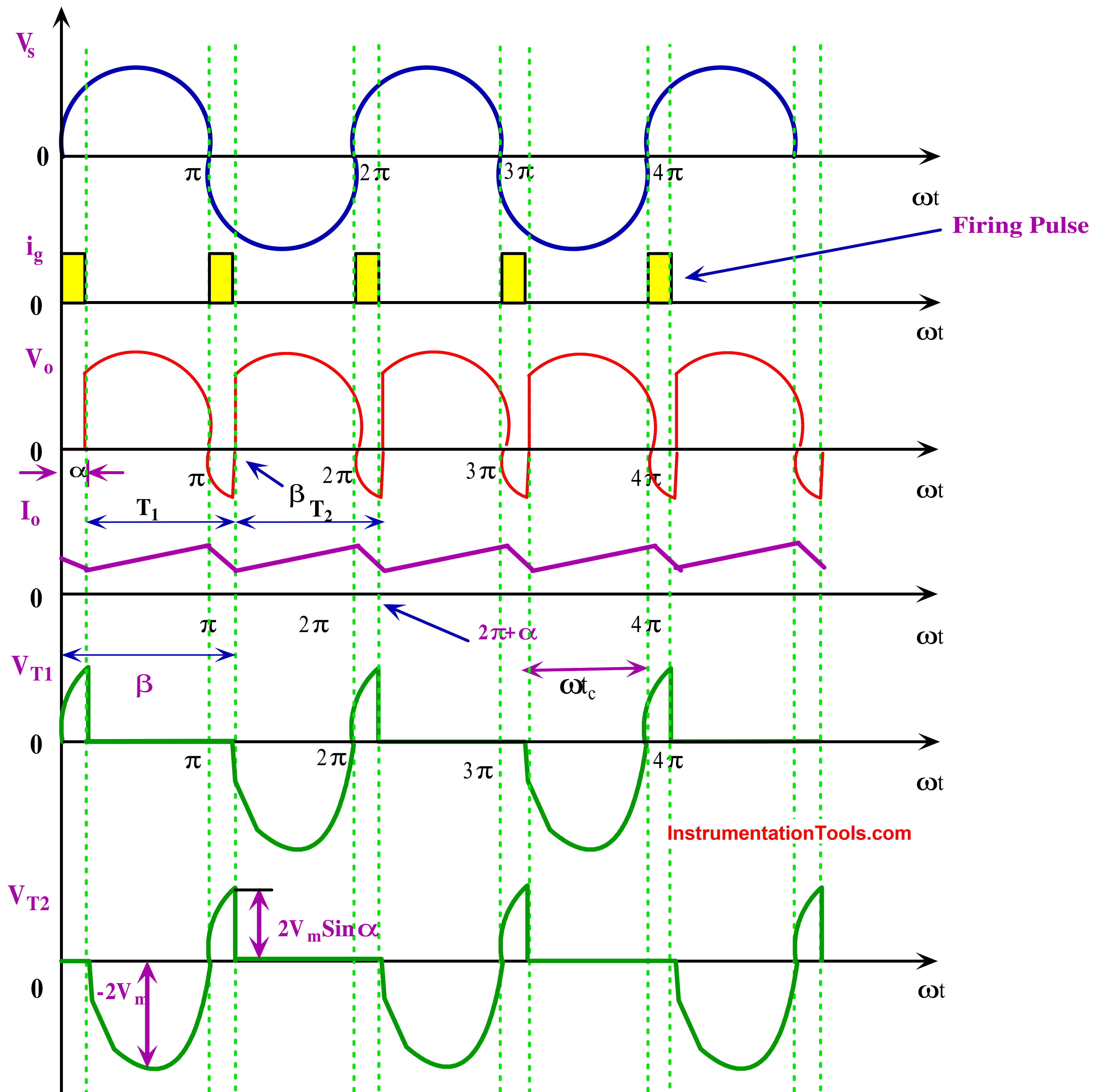
Fig 4.2 Full Controlled Rectifier With RL Load Output Waveform
Matlab Simulation Results
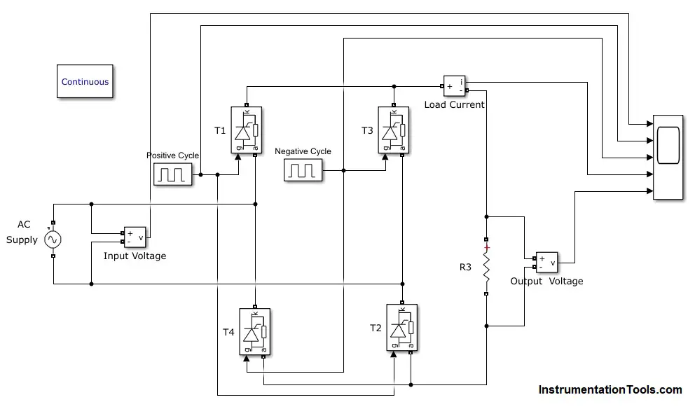
Fig 5. Single Phase Full Bridge Converter With R Load
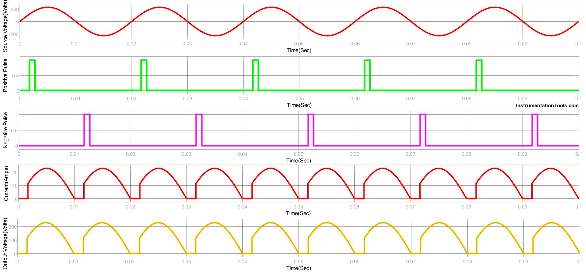
Fig 6. Simulink Circuit of Full-controlled Rectifier R Load
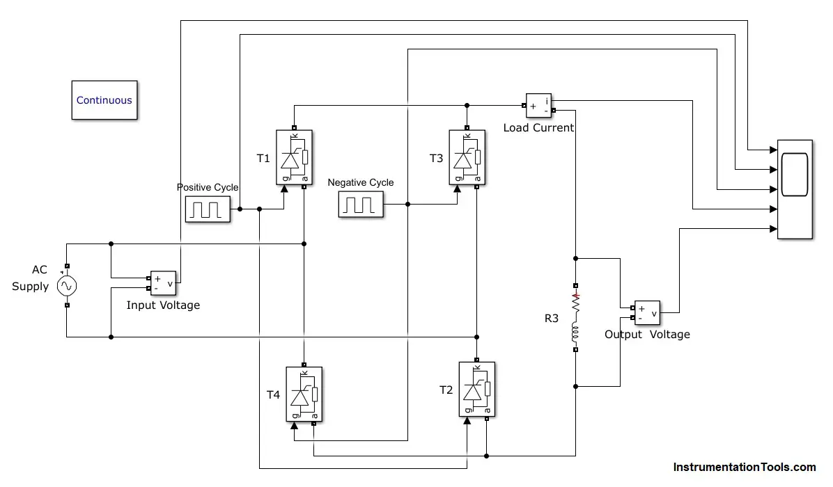
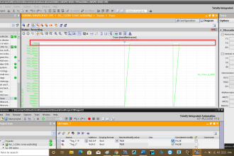
Fig 7. Simulink Response of Full-controlled Rectifier R Load
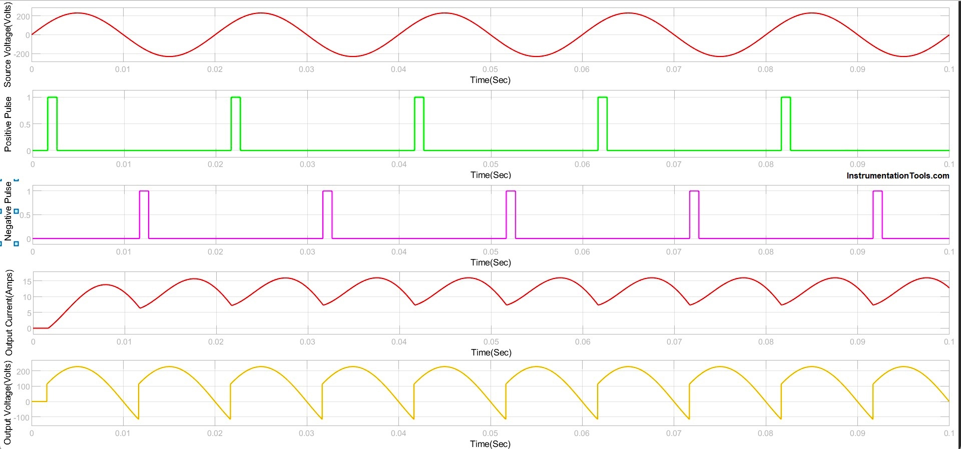
Fig 8. Simulink Response of Full-controlled Rectifier R Load
Advantages of Full-wave Rectifier
- Single-phase full converters are relatively simple in design compared to their three-phase counterparts, making them cost-effective and easy to implement in various applications.
- Full converters can handle both inductive (RL) and resistive (R) loads, making them versatile for different types of applications.
- Full converters can be configured to allow regenerative braking in certain applications, where energy can be returned to the source from the load during deceleration.
- Single-phase full converters can be designed to generate low harmonics in the output waveform, reducing electrical noise in the system.
Disadvantages of Full-wave Rectifier
- Single-phase full converters can have a poor power factor, especially when operating with inductive loads. This leads to increased reactive power consumption and can cause inefficiency in the system.
- The output voltage of the converter can have significant ripples, especially at lower power levels. This can affect the performance of sensitive electronic devices.
- Achieving precise control over the output voltage and current requires sophisticated control techniques, which can complicate the design and increase the cost.
- Single-phase systems inherently have limitations in terms of the power they can handle. For high-power applications, three-phase converters are preferred due to their higher power capacity.
- The components of the converter, especially semiconductor devices like thyristors, can experience thermal stress due to high currents flowing through them. This necessitates efficient cooling systems, adding complexity and cost to the setup.
If you liked this article, then please subscribe to our YouTube Channel for Instrumentation, Electrical, PLC, and SCADA video tutorials.
You can also follow us on Facebook and Twitter to receive daily updates.
Read Next:
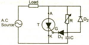
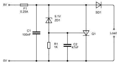
- Thyristor Protection Circuits (SCR)
- Top 100 Power Electronics Projects
- Thyristor Triggering Circuits and Types
- Phase Controlled Half Wave Rectifier RL Load
- Half-Wave Rectifier With Freewheeling Diode