A timer is a PLC instruction measuring the amount of time elapsed following an event.
Timer instructions come in two basic types: on-delay timers and off-delay timers. Both “on-delay” and “off-delay” timer instructions have single inputs triggering the timed function.
An “on-delay” timer activates an output only when the input has been active for a minimum amount of time.
PLC Timer Instructions
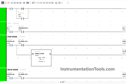
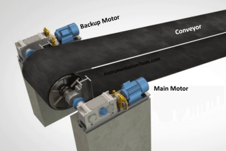
Take for instance this PLC program, designed to sound an audio alarm siren prior to starting a conveyor belt.
To start the conveyor belt motor, the operator must press and hold the “Start” push-button for 10 seconds, during which time the siren sounds, warning people to clear away from the conveyor belt that is about to start.
Only after this 10-second start delay does the motor actually start (and latch “on”):


Similar to an “up” counter, the on-delay timer’s elapsed time (ET) value increments once per second until the preset time (PT) is reached, at which time its output (Q) activates.
In this program, the preset time value is 10 seconds, which means the Q output will not activate until the “Start” switch has been depressed for 10 seconds.
The alarm siren output, which is not activated by the timer, energizes immediately when the “Start” push-button is pressed.
An important detail regarding this particular timer’s operation is that it be non-retentive.
This means the timer instruction should not retain its elapsed time value when the input is de-activated.
Instead, the elapsed time value should reset back to zero every time the input de-activates. This ensures the timer resets itself when the operator releases the “Start” push-button.
A retentive ondelay timer, by contrast, maintains its elapsed time value even when the input is de-activated. This makes it useful for keeping “running total” times for some event.
Also Read : PLC Math Instructions
Most PLCs provide retentive and non-retentive versions of on-delay timer instructions, such that the programmer may choose the proper form of on-delay timer for any particular application.
The IEC 61131-3 programming standard, however, addresses the issue of retentive versus non-retentive timers a bit differently.
According to the IEC 61131-3 standard, a timer instruction may be specified with an additional enable input (EN) that causes the timer instruction to behave non-retentively when activated, and retentively when de-activated.
The general concept of the enable (EN) input is that the instruction behaves “normally” so long as the enable input is active (in this case, non-retentive timing action is considered “normal” according to the IEC 61131-3 standard), but the instruction “freezes” all execution whenever the enable input de-activates.
This “freezing” of operation has the effect of retaining the current time (CT) value even if the input signal de-activates.
For example, if we wished to add a retentive timer to our conveyor control system to record total run time for the conveyor motor, we could do so using an “enabled” IEC 61131-3 timer instruction like this:

When the motor’s contactor bit (OUT contactor) is active, the timer is enabled and allowed to time.
However, when that bit de-activates (becomes “false”), the timer instruction as a whole is disabled, causing it to “freeze” and retain its current time (CT) value ( Note 1 ).
This allows the motor to be started and stopped, with the timer maintaining a tally of total motor run time.
Note 1 : The “enable out” (ENO) signal on the timer instruction serves to indicate the instruction’s status: it activates when the enable input (EN) activates and de-activates when either the enable input de-activates or the instruction generates an error condition (as determined by the PLC manufacturer’s internal programming). The ENO output signal serves no useful purpose in this particular program, but it is available if there were any need for other rungs of the program to be “aware” of the run-time timer’s status.
If we wished to give the operator the ability to manually reset the total run time value to zero, we could hard-wire an additional switch to the PLC’s discrete input card and add “reset” contacts to the program like this:

Whenever the “Reset” switch is pressed, the timer is enabled (EN) but the timing input (IN) is disabled, forcing the timer to (non-retentively) reset its current time (CT) value to zero.
The other major type of PLC timer instruction is the off-delay timer. This timer instruction differs from the on-delay type in that the timing function begins as soon as the instruction is deactivated, not when it is activated.
An application for an off-delay timer is a cooling fan motor control for a large industrial engine.
In this system, the PLC starts an electric cooling fan as soon as the engine is detected as rotating, and keeps that fan running for two minutes following the engine’s shut-down to dissipate residual heat:

When the input (IN) to this timer instruction is activated, the output (Q) immediately activates (with no time delay at all) to turn on the cooling fan motor contactor.
This provides the engine with cooling as soon as it begins to rotate (as detected by the speed switch connected to the PLC’s discrete input).
When the engine stops rotating, the speed switch returns to its normally-open position, de-activating the timer’s input signal which starts the timing sequence.
The Q output remains active while the timer counts from 0 seconds to 120 seconds.
As soon as it reaches 120 seconds, the output de-activates (shutting off the cooling fan motor) and the elapsed time value remains at 120 seconds until the input re-activates, at which time it resets back to zero.
The following timing diagrams compare and contrast on-delay with off-delay timers:

While it is common to find on-delay PLC instructions offered in both retentive and non-retentive forms within the instruction sets of nearly every PLC manufacturer and model, it is almost unheard of to find retentive off-delay timer instructions. Typically, off-delay timers are non-retentive only (Note 2 ).
Note 2 : The enable (EN) input signals specified in the IEC 61131-3 programming standard make retentive off-delay timers possible (by de-activating the enable input while maintaining the “IN” input in an inactive state), but bear in mind that most PLC implementations of timers do not have separate EN and IN inputs. This means (for most PLC timer instructions) the only input available to activate the timer is the “IN” input, in which case it is impossible to create a retentive off-delay timer (since such a timer’s elapsed time value would be immediately re-set to zero each time the input re-activates).
Credits : by Tony R. Kuphaldt – Creative Commons Attribution 4.0 License
PLC Tutorials :
What is Programmable Logic Controller ?
What is Ladder Diagram Programming ?
History of Programmable Logic Controllers
Mis-conceptions of PLC Ladder Logic
Contacts and coils in PLC
Digital Input and Output Modules
Analog I/O and Network I/O
PLC Input/Output Modules
Memory Mapping in PLC
Analog Input Scaling
PLC Example with Switches
Counter Instructions
Timer Instructions
Math instructions
Data Instructions
Ladder Logic Questions
If you liked this article, then please subscribe to our YouTube Channel for PLC and SCADA video tutorials.
You can also follow us on Facebook and Twitter to receive daily updates.