Write the PLC program for temperature control with PWM output of PID.
Temperature control with PWM output of PID
Solution
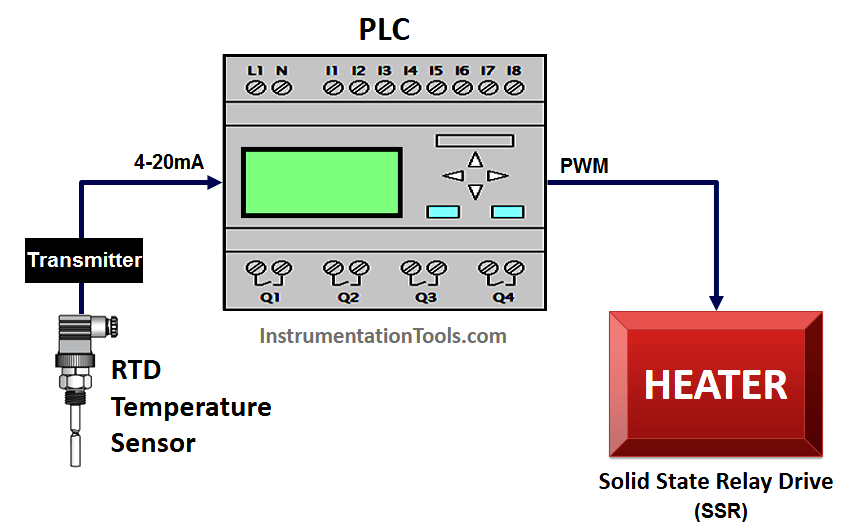
Here we use RTD sensor for temperature measurement and a transmitter to convert sensor output into standard 4-20mA current output, which is then connected to PLC input.
RTD sensor will detect temperature and transmitter will generate signal according to measured temperature.
Solid State Relay (SSR) drive is used to control the heater and SSR will be controlled by PWM (pulse width modulation) output of PLC. Solid State Relay Drive will control the heater power supply in-order to maintain the required temperature.
For example, if PLC output PWM varies from range 0 to 100% then accordingly SSR will control the Heater power supply, so we can maintain the heater temperature.
PID controller will generate PWM as per temperature input signal feedback.
List of Inputs/Outputs
List of Inputs
- Temperature Analog input :- IW64
List of Outputs
- PWM output for heater (SSR) : Q1.1
M memory
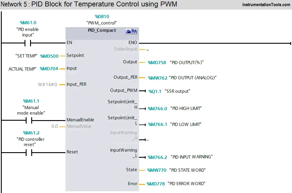
- PID enable :- M61.0
- Manual enable :- M61.1
- PID reset :- M61.2
- Set temperature :- MD500
- Actual temperature :- MD704
- PID output (%) :- MD758
- PID state word :- MW770
- PID error word :- MD778
- PID enable input :- M61.0
- PID manual mode enable input :- M61.1
- PID controller reset :- M61.2
- PID high limit alarm :- M766.0
- PID low limit alarm:-M766.1
- PID input warning:-M766.2
Ladder diagram for Temperature control with PWM of PID
Program Description
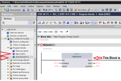
For this application we used S7-1200 PLC and TIA portal software for programming.
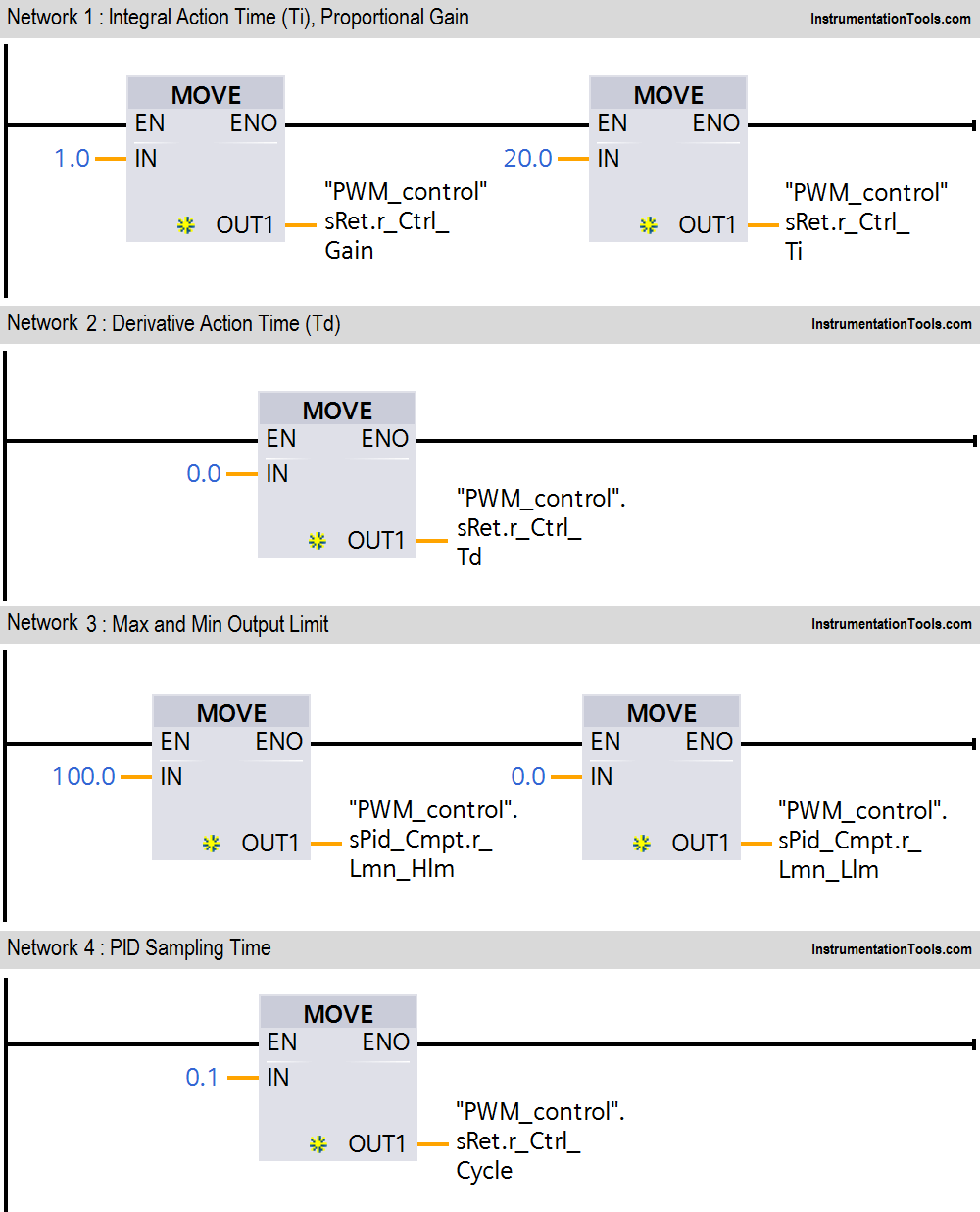
Network 1 :
In network we configured standard parameters for PID function.
“Drive PID”.sRet.r_Ctrl_Gain:- saved proportional gain or P gain for PID (1.0).
“Drive PID”.sRet.r_Ctrl_Ti:-Saved integral time or I gain for PID (20s).
Network 2 :
“Drive PID”.sRet.r_Ctrl_Td:-Saved derivative time or D gain for PID (0s).
Network 3 :
Here we have taken temperature PID max output limit and minimum output limit. We have considered here max limit for PID output 100 and minimum limit is 0.
Network 4 :
Sampling time of the PID_Compact instruction r_Cycle is determined automatically and usually equivalent to the cycle time of the calling OB.
Consider 0.1s for this application.
Network 5 :
Here we used PID controller which will control the SSR by providing PWM output.
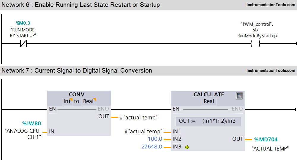
Network 6 :
PID run mode control enabled.
Network 7 :
Here we converted current (4-20mA) input signal into digital (0- 27648) signal.
Note :- Above application may be different from actual application. This example is only for explanation purpose only. We can implement this logic in other PLC also. This is the concept of temperature control with PWM of PID, we can use this concept in other examples also.
All parameters and graphical representations considered in this example are for explanation purpose only, parameters or representation may be different in actual applications. Also all interlocks are not considered in the application.
If you liked this article, then please subscribe to our YouTube Channel for PLC and SCADA video tutorials.
You can also follow us on Facebook and Twitter to receive daily updates.
Read Next:
Top 100 PLC Objective Questions
Instrumentation Functional diagrams
PLC Analog Input Card Resolution
Programmable Logic Controller Quiz






Give some example of Split range control with PWM output of PID