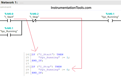
Example of PLC programming based on the logic circuit using Schneider Electric EcoStruxure Machine Expert Basic.
PLC Programming based on Logic Circuit
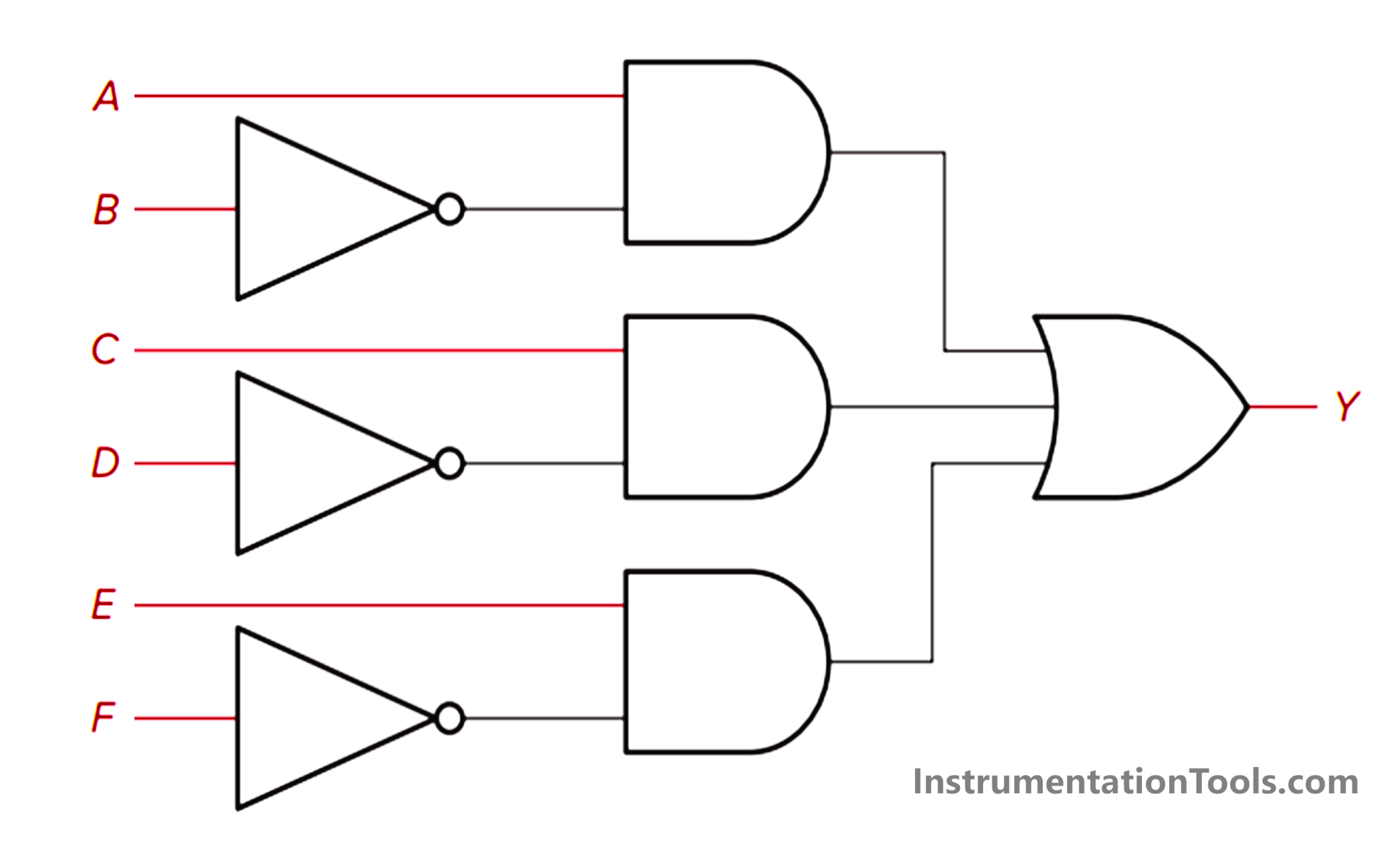
Design a PLC ladder logic for the following Logic Circuit.
We are using toggle Inputs to control the output.
PLC Learning Videos for Beginners
In this video, we explained this PLC programming example with details for beginners.
Program I/O Details
Digital Inputs:
- A: I0.0
- B: I0.1
- C: I0.2
- D: I0.3
- E: I0.4
- F: I0.5
Digital Outputs:
- Y: Q0.0
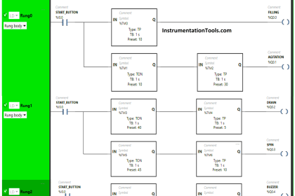
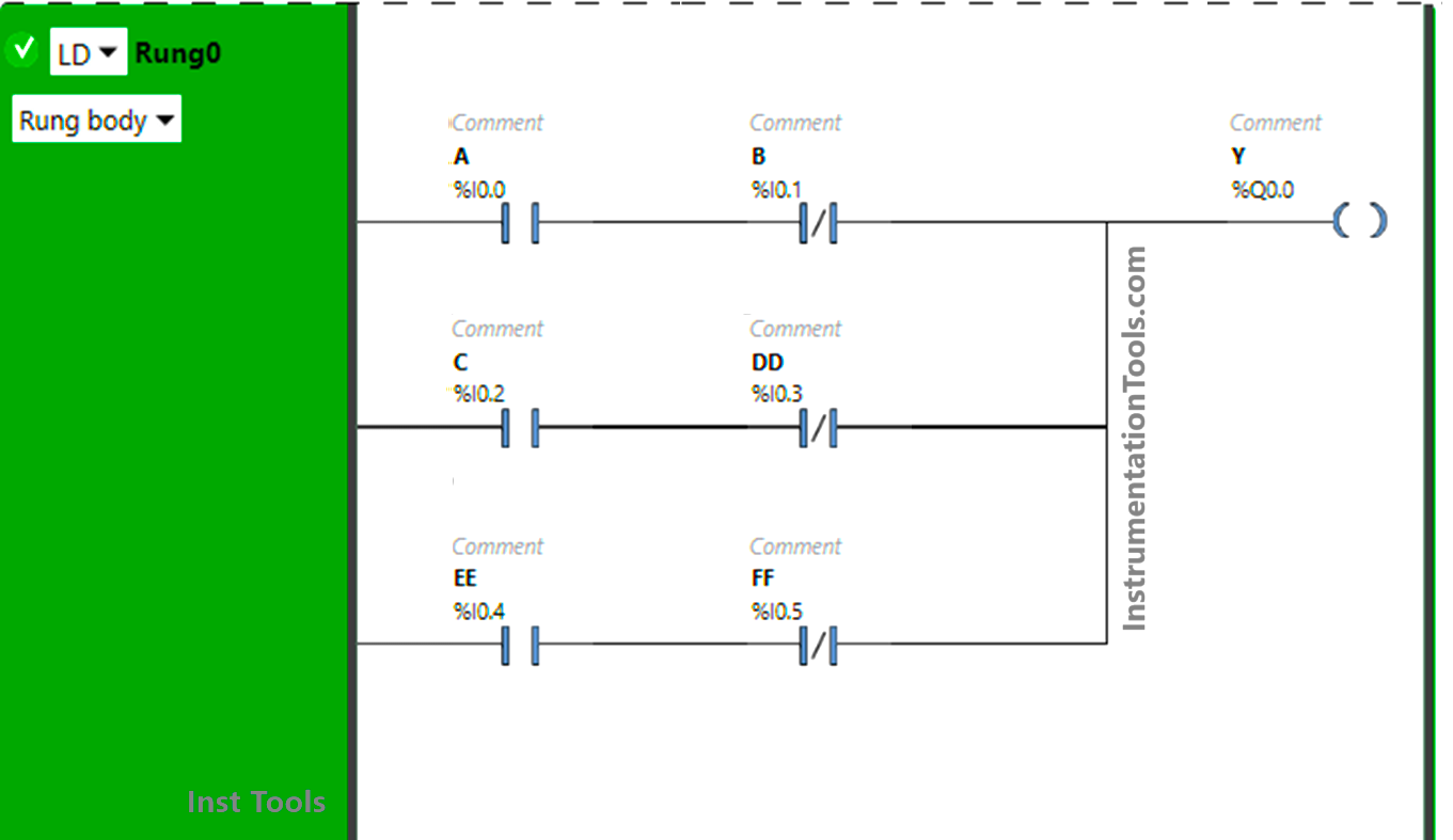
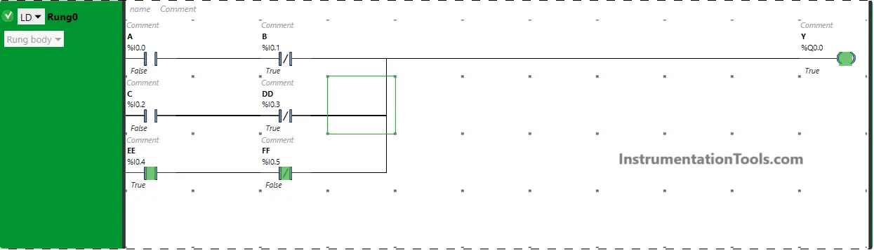
Ladder Logic
Here is the answer to the given PLC problem.
PLC Program Description
- For this application, we have used EcoStruxure Machine Expert Basic software for programming.
- In the above program, Normally Open Contacts are used for inputs A, C, and E and Normally Closed Contacts are used for inputs B, D, F.
- Input A and Input B are connected in series, thus implementing AND Logic Gate.
- AND Logic Gate is implemented with Input C and Input D as these Inputs are connected in series.
- Input E and Input F are connected in series, thus implementing AND Logic Gate.
- AB, CD, and EF are connected in parallel, thus implementing OR Logic Gate.
- For the output Y (Q0.0) to be ON, either Input A should be ON and Input B should be OFF or Input C should be ON and Input D should be OFF or Input E should be ON and Input F should be OFF.
- If Input B, Input D, and Input F are turned ON, output Y (Q0.0) will not turn ON as Normally Closed Contacts used for these Inputs will be in True state and does not allow the signal to flow and pass to the output.
Program Simulation Analysis
When Input A is ON and Input B is OFF
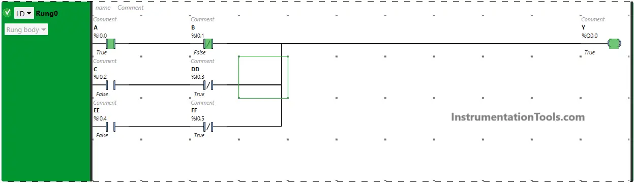
The signal flow through Input A and Input B as Normally Open Contact used for Input A is in True state and Normally Closed Contact used for Input B is in the false state will pass the signal to output and the output Y (Q0.0) will turn ON. If Input B is turned ON, the signal does not flow through Input B. In True state Normally Closed Contacts break the circuit.
When Input B is ON and Input D is OFF
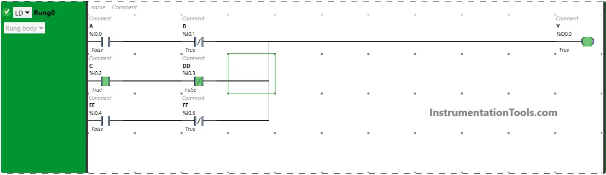
The output Y (Q0.0) will turn ON when Input B is turned ON and Input D is turned OFF because Input B is in the true state as Normally Open Contact is used for this Input and Normally Closed Contact used for Input D is in the false state. If Input D is turned ON, the signal does not flow through Input D. In True state Normally Closed Contacts break the circuit.
When Input E is ON and Input F is OFF
When Input E is turned ON and Input F is turned OFF, the output Y (Q0.0) will turn ON as Normally Open Contact used for Input E will allow signal to pass and also Input F will pass signal to output because Normally Closed Contact used for Input F is in false state.
When Input A, Input C, Input E are ON and Input B, Input D, Input F are OFF

When Input A, Input C, Input E are turned ON and Input B, Input D, Input F are turned OFF, the output Y (Q0.0) will turn OFF because all Normally Open Contacts will be in true state and all Normally Closed Contacts will be in false state. So, signal will flow through these Inputs and Y(Q0.0) will turn ON.
Read Next:
- PLC Product Sticker Machine with Weighing
- Start Stop of one Motor from the PLC Logic
- Waste-Burning System OMRON PLC Logic
- Water Pump PLC Program CX-Programmer
- Create PLC Program based on Logic Circuit