This article will teach you the PLC Program with 2 Toggle Switches and 4 Motors logic diagrams.
Note: The logic diagram example is for students and engineering graduates to learn the PLC basics.
PLC Program with 2 Toggle Switches
Problem Statement
Design a PLC ladder logic for the following application.
We are using two toggle switches to control four motors.
If Switch 1 is ON, then Motor I and Motor II will be ON.
If Switch 1 is OFF, then Motor I will be OFF and Motor II will be ON.
If Switch 2 is ON, then Motor III and Motor IV will be ON.
If Switch 2 is OFF, then Motor III will be OFF and Motor I will be ON.
Schneider Electric PLC Example
Watch this PLC video to learn the programming example.

Input Details
Digital Inputs:
This program’s required digital inputs are mentioned below.
Switch 1: I0.0
Switch 2: I0.1
Output Details
Digital Outputs:
This program’s required digital outputs are mentioned below.
Motor 1: Q0.0
Motor 2: Q0.1
Motor 3: Q0.2
Motor 4: Q0.3
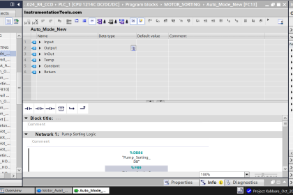
2 Toggle Switches and 4 Motors Logic
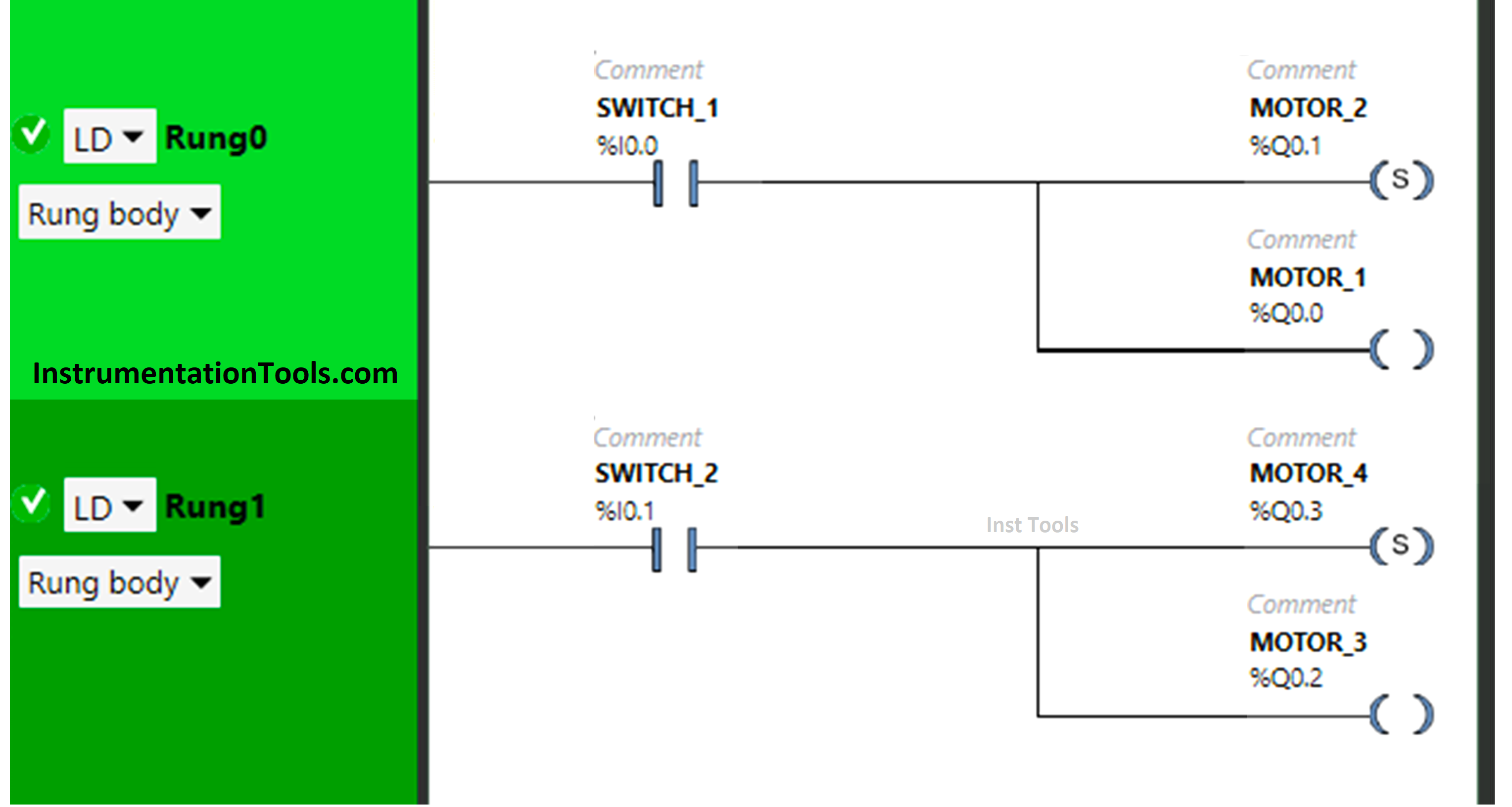
Logic Diagram Explanation
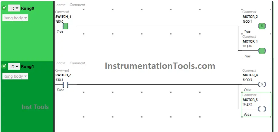
We used EcoStruxure Machine Expert Basic PLC software for this example logic.
In the above program, we have used Normally Open Contact for Switch 1 (I0.0) and Switch 2 (I0.1).
We have used a Set Coil for Motor 2 (Q0.1), Motor 4 (Q0.3), and a normal Coil for Motor 1 (Q0.0), and Motor 3 (Q0.2).
For Motor 1 and Motor 2 to be ON, switch 1 should be ON
When Switch 1 is turned OFF, Motor 1 will turn OFF but Motor 2 will remain ON as we have used Set Coil for it.
Turning ON Switch 2 will turn ON Motor 3 and Motor 4.
Motor 3 will turn OFF when Switch 2 is turned OFF but Motor 4 for which the Set coil is used remains ON.
PLC Logic Result
Now we will see the PLC logic result with different input scenarios.
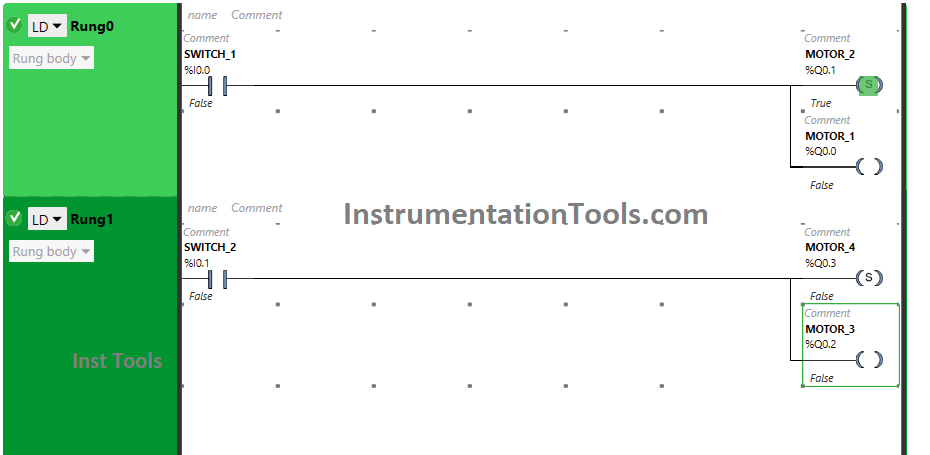
When Switch 1 is ON
The signal flows through switch 1 as it is in true state, both Motor 1 and Motor 2 will turn ON.
When Switch 1 is OFF
When switch 1 is turned OFF, Motor 1 will turn OFF and Motor 2 still remains ON as SET coil is used for Motor 2.
When Switch 2 is ON
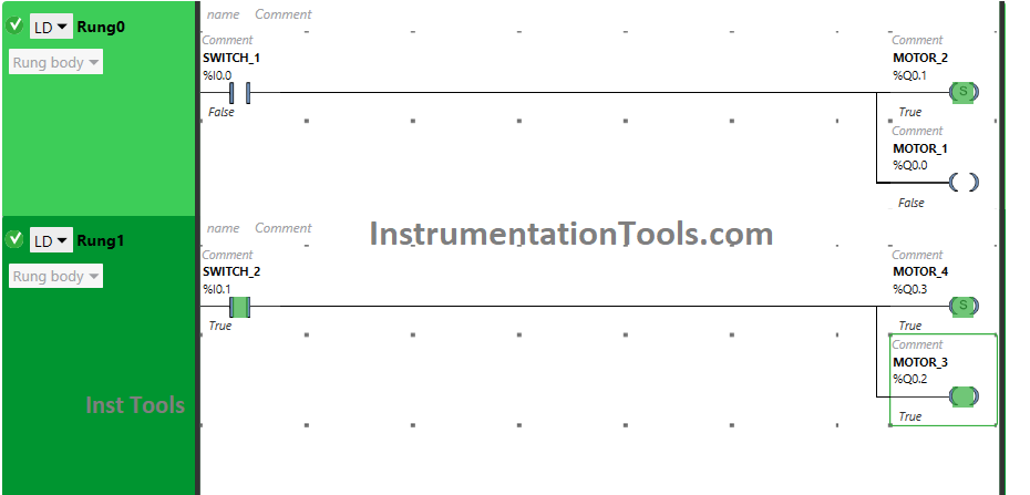
Motor 3 and Motor 4 will turn ON when switch 2 is turned ON. The input Switch 2 is used as Normally open Contact, in the true state, which will allow the signal to pass through it.
When Switch 2 is OFF
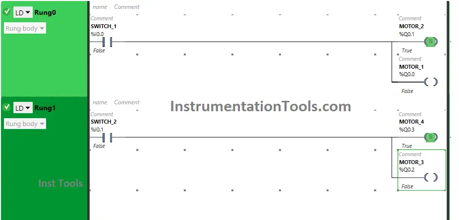
After turning OFF switch 2, Motor 3 will turn OFF and Motor 4 will remain ON in which SET coil is used.
If you liked this article, please subscribe to our YouTube Channel for PLC and SCADA video tutorials.
You can also follow us on Facebook and Twitter to receive daily updates.
Read Next:
- Tags in Siemens Scada and PLC
- How to Get a PLC Programmer Job?
- Add Unspecified CPU in Tia Portal
- PLC Based Product Sorting Machine
- Password Protect HMI in Siemens TIA Portal?