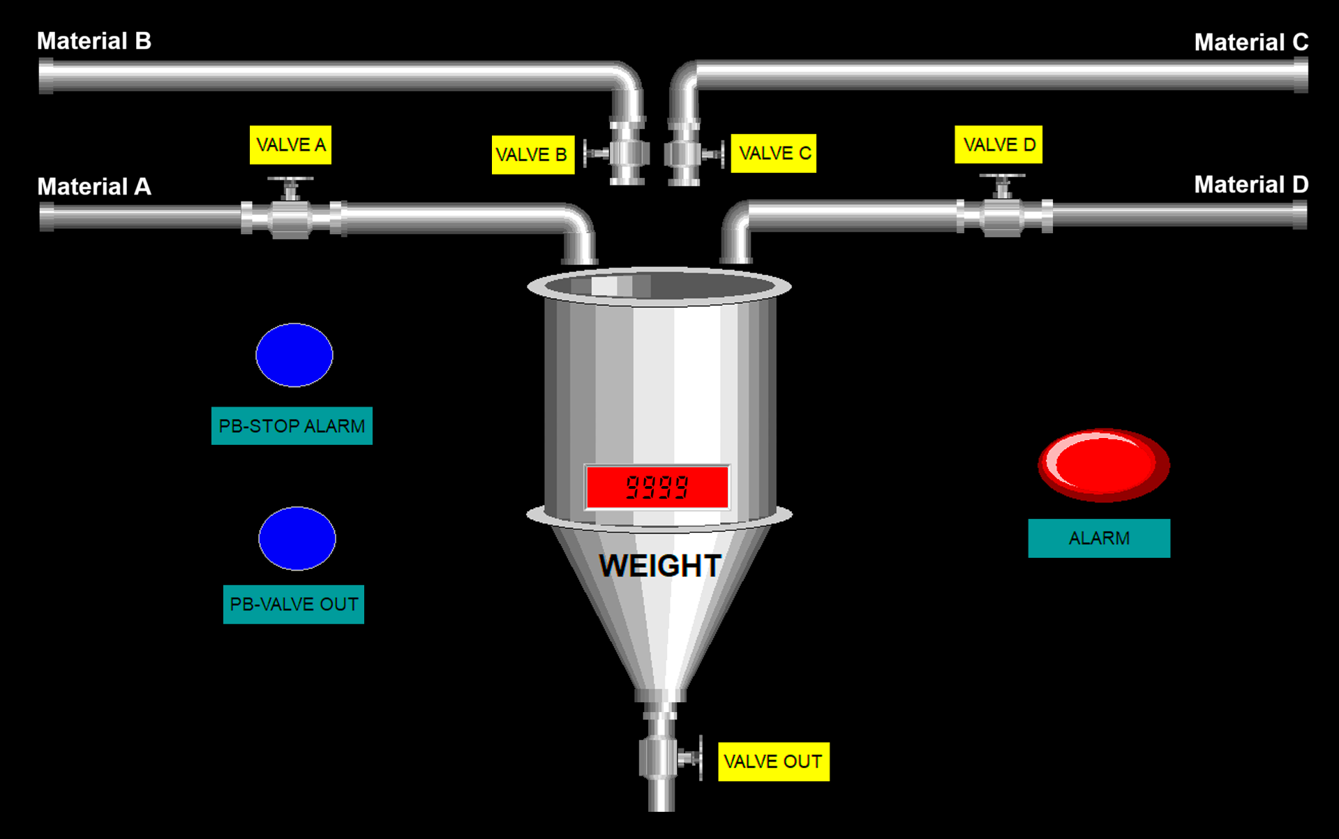
This article will discuss a raw material mixing system using Omron PLC programming. The system will mix four different raw materials in a single tank. The raw materials will be mixed using two measurement methods: weight-based and time-based. During the mixing process, the raw materials will be heated and cooled over a specific time period. The system will provide an alarm indicator once the entire sequence of processes has been completed.
Program Objective
Raw Material Processing Procedure:
System Initialization:
The system will mix four raw materials in the predetermined process sequence.
Material Filling Process:
- Material A is added to the tank with a weight of 5 kg.
- Material B is added to the tank with a weight of 10 kg.
- The mixer is activated to blend the materials.
- Material C is added to the tank by opening the valve for 3 seconds.
- The heater is activated and operates for 10 seconds.
- Material D is added to the tank by opening the valve for 4 seconds.
Cooling Process:
The cooling fan is activated and operates for 10 seconds.
End of Process:
- The mixer is turned off.
- The alarm indicator lights up to signal the process completion.
System Reset:
- The system can only be restarted if the tank is empty.
- The outlet valve can only be operated manually.
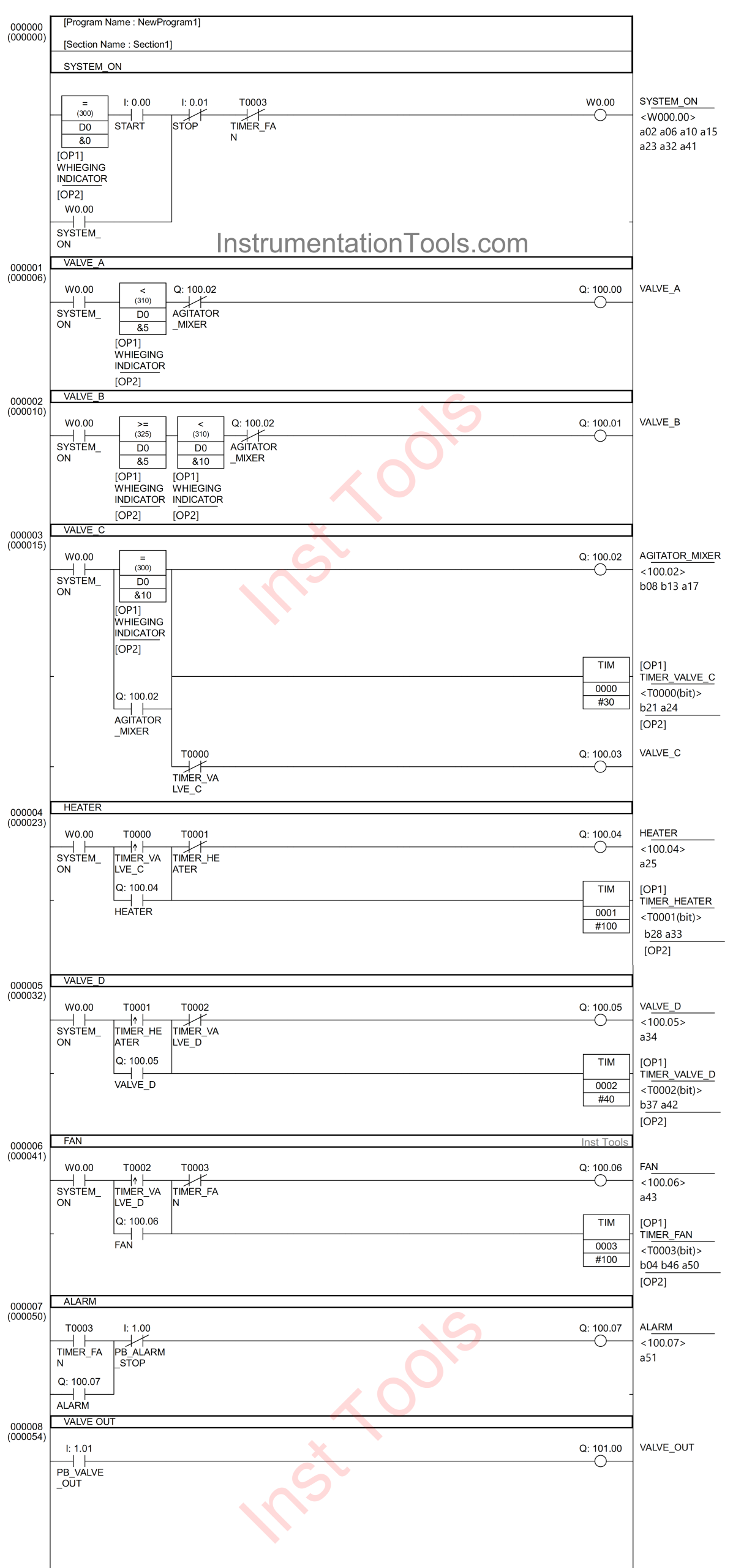
PLC Program to Mix 4 Materials
IO Mapping
| S.No. | Comment | Input (I) | Output (Q) | Memory Bit | Memory Word | Timers |
|---|---|---|---|---|---|---|
| 1 | START | 0.00 | ||||
| 2 | STOP | 0.01 | ||||
| 3 | PB_ALARM_STOP | 1.00 | ||||
| 4 | PB_VALVE_OUT | 1.01 | ||||
| 5 | VALVE_A | 100.00 | ||||
| 6 | VALVE_B | 100.01 | ||||
| 7 | AGITATOR_MIXER | 100.02 | ||||
| 8 | VALVE_C | 100.03 | ||||
| 9 | HEATER | 100.04 | ||||
| 10 | VALVE_D | 100.05 | ||||
| 11 | FAN | 100.06 | ||||
| 12 | ALARM | 100.07 | ||||
| 13 | VALVE_OUT | 101.00 | ||||
| 14 | WHIEGING INDICATOR | D0 | ||||
| 15 | TIMER_VALVE_C | T0000 | ||||
| 16 | TIMER_HEATER | T0001 | ||||
| 17 | TIMER_VALVE_D | T0002 | ||||
| 18 | TIMER_FAN | T0003 | ||||
| 19 | SYSTEM_ON | W0.00 |
Programming Explanation
RUNG 0 (SYSTEM_ON)
In this Rung, if the value of the memory word WHIEGING INDICATOR (D0) is Equal to “0” and the START (0.00) button is pressed, then the memory bit SYSTEM_ON (W0.00) will be in the HIGH state. Because it uses Latching, the memory bit SYSTEM_ON (W0.00) will remain in the HIGH state even though the PB_START (0.00) button has been released.
The memory bit SYSTEM_ON (W0.00) will return to the LOW state if the STOP (0.01) button is pressed or the NC contact of the timer TIMER_FAN (T0003) is in the HIGH state.
RUNG 1 (VALVE_A)
In this Rung, when the NO contact of the memory bit SYSTEM_ON (W0.00) is in HIGH state and the value of the memory word WIEGHING INDICATOR (D0) is Less than “5”, then the VALVE_A (100.00) output will be OPEN.
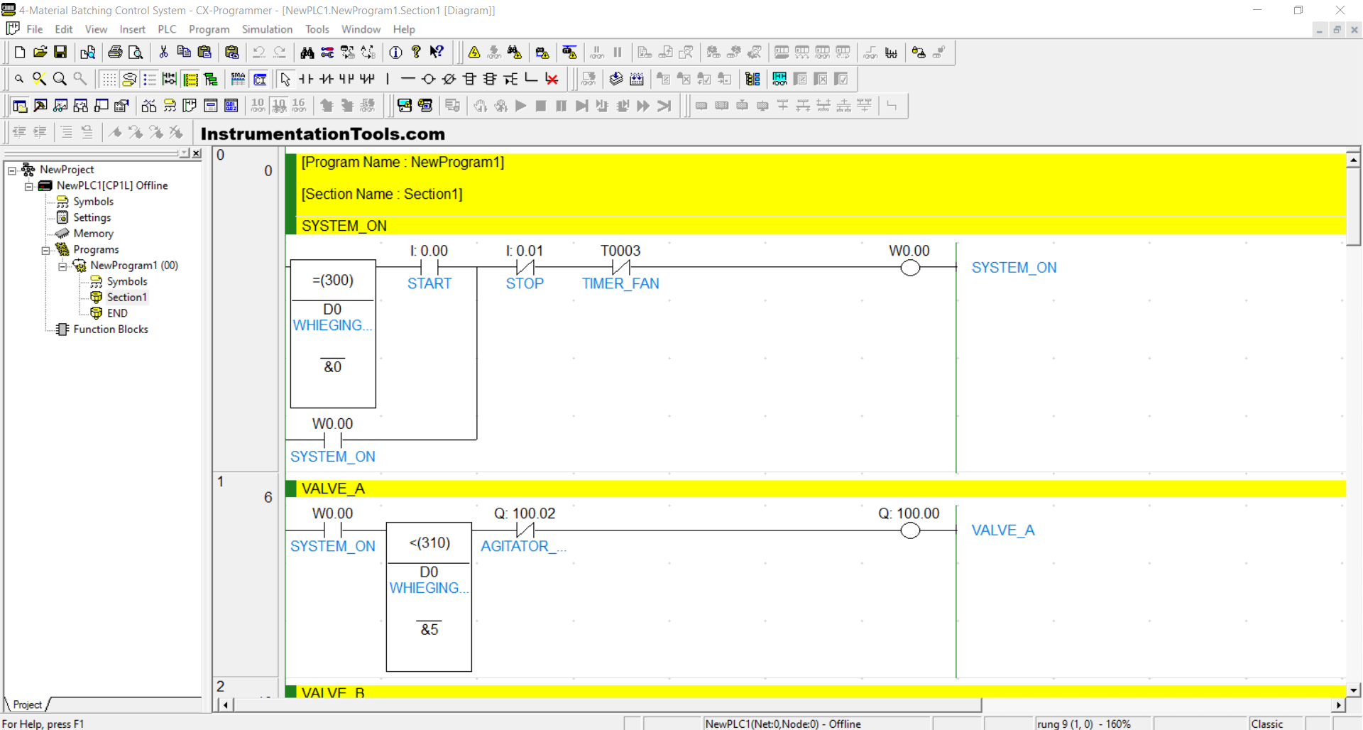
RUNG 2 (VALVE_B)
When the NO contact of the memory bit SYSTEM_ON (W0.00) is in the HIGH state and the value of the memory word WIEGHING INDICATOR (D0) is Greater than or Equal to “5” and Less than “10”, then the VALVE_B (100.01) output will be OPEN.
The VALVE_B (100.01) output will be CLOSED if the NC contact of the AGITATOR_MIXER (100.02) is in the HIGH state.
RUNG 3 (VALVE_C)
When the NO contact of the memory bit SYSTEM_ON (W0.00) is in the HIGH state and the value of the memory word WEIGHING INDICATOR (D0) is Equal to “10”, then the AGITATOR_MIXER (100.02) output will be ON and the VALVE_C (100.03) output will be OPEN.
The TIMER_VALVE_C (T0000) timer will start counting up to 3 seconds, and after finishing counting, the VALVE_C (100.03) output will be CLOSED.
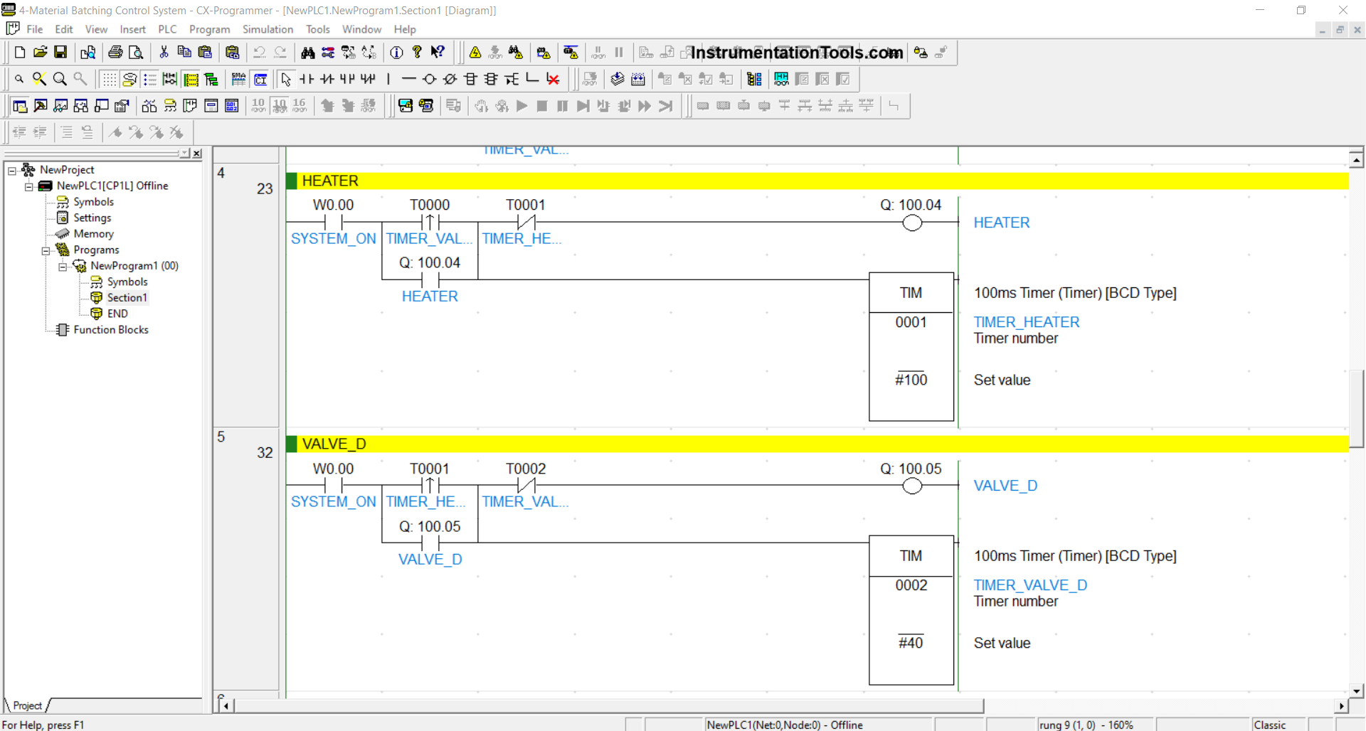
RUNG 4 (HEATER)
When the NO contact of the memory bit SYSTEM_ON (W0.00) and the TIMER_VALVE_C (T0000) timer are in the HIGH state, the HEATER (100.04) output will be ON. Because it uses Latching, the HEATER (100.04) output will remain ON even though the NO contact of the TIMER_VALVE_C (T0000) timer is in the LOW state.
The TIMER_HEATER (T0001) timer will start counting up to 4 seconds, and once the counting is complete, the HEATER (100.04) output will be OFF.
RUNG 5 (VALVE_D)
When the NO contact of the memory bit SYSTEM_ON (W0.00) and the TIMER_HEATER (T0001) timer are in the HIGH state, the VALVE_D (100.05) output will be OPEN. Because it uses Latching, the VALVE_D (100.05) output will remain OPEN even though the NO contact of the TIMER_HEATER (T0001) timer is in the LOW state.
The TIMER_ VALVE_D (T0002) timer will start counting up to 4 seconds, and once the counting is complete, the VALVE_D (100.05) output will be CLOSED.
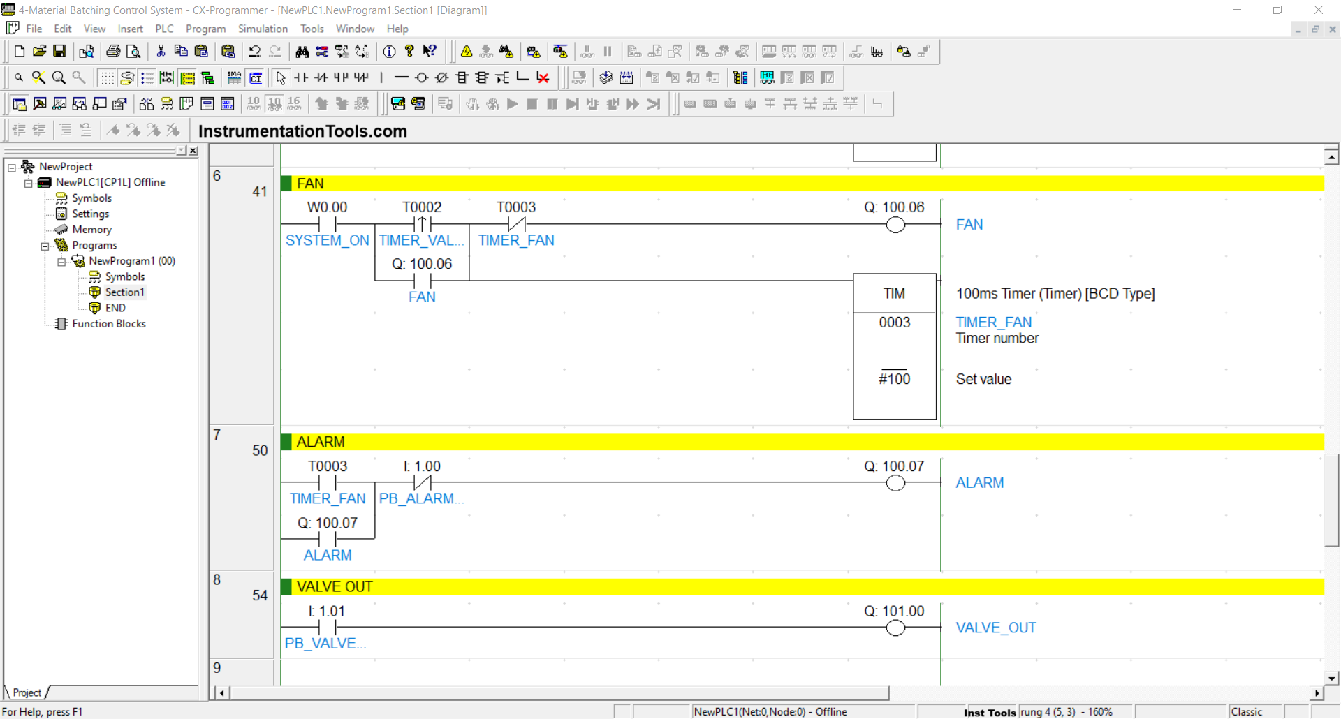
RUNG 6 (FAN)
When the NO contact of the memory bit SYSTEM_ON (W0.00) and the TIMER_ VALVE_D (T0002) timer are in the HIGH state, the FAN (100.06) output will be ON. Because it uses Latching, the FAN (100.06) output will remain ON even though the NO contact of the TIMER_ VALVE_D (T0002) timer is in the LOW state.
The TIMER_ FAN (T0003) timer will start counting up to 10 seconds, and after counting is complete, the FAN (100.06) output will be OFF.
RUNG 7 (ALARM)
When the NO contact of the TIMER_ FAN (T0003) timer is in the HIGH state, the ALARM (100.07) output will be ON. Because it uses Latching, the ALARM output (100.07) will remain ON even though the NO contact of the TIMER_ FAN timer (T0003) is in the LOW state.
The ALARM output (100.07) will be OFF if the PB_ALARM_STOP button (1.00) is pressed.
RUNG 8 (VALVE OUT)
The VALVE_OUT output (101.00) will be OPEN if the PB_VALVE_OUT button (1.01) is pressed.
Read Next:
- Chemical Mixing Process using PLC Ladder Logic
- Measure the Speed of a Conveyor using PLC Programming
- Omron PLC Programming for 4 Conveyor Interlock System
- Heating and Mixing of Products using PLC Example
- PLC Programming for Automatic Mixing Control in a Tank


am interested on automation training