This is the PLC Program to implement D flip flops in PLC. Learn PLC programming based on simple digital electronics examples.
D Flip Flop PLC Ladder Logic
Problem Description
Implement D flip flop in PLC using ladder language programming.
Problem Diagram

Problem Solution
D flip flop has one input which denoted with D. D latch is simple flip flop with NAND gate circuit between S and R input.
In SR flip flop when S=R=1 and S=R=0, outputs either do not change or they are invalid (no action).
As we can see in diagram in D flip flop S and R inputs always be the complements of each other. Hence S=R=1 and S=R=0 conditions will never occur.
This disadvantage of the SR flip flop can be overcome by using D flip flop.
Truth Table for the D Latch

List of inputs and outputs
Digital Inputs
- SET/RESET :- I0.0
Digital outputs
- Q output :- Q0.0
- Q^ output :- Q0.1
M memory
- Relay coil 1 :- M0.0
- Relay coil 2 :- M0.1
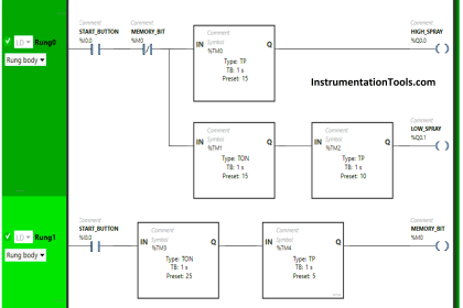
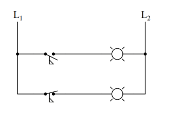
PLC Ladder Diagram for D-Flipflop
Program Description
For this application, we use S7-300 PLC and TIA portal software for programming. We can implement this logic by using other PLC also.
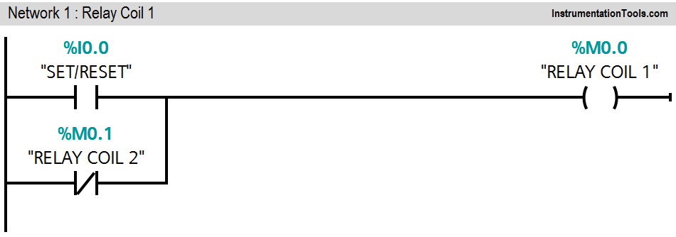
Network 1:
Here we used NO contact of SET/RSET input (I0.0) and in parallel connection we used NC contact of relay coil 2 (M0.1) to operate relay coil 1 (M0.0).
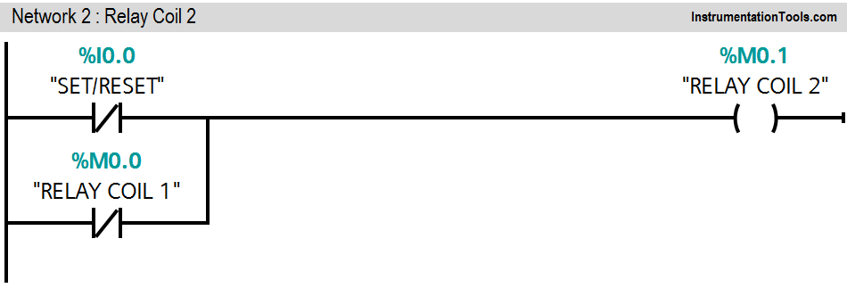
Network 2:
Here we used NC contact of SET/RSET input (I0.0) and in parallel connection we used NC contact of relay coil 1 (M0.0) to operate relay coil 2 (M0.1).
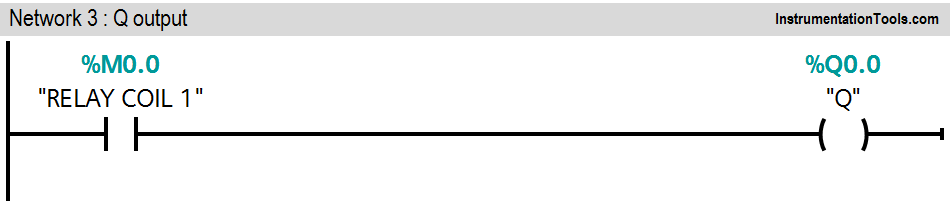
Network 3:
When relay coil 1 (M0.0) is ON, Q output (Q0.0) will be ON.
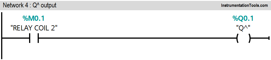
Network 4:
When relay coil 2 (M0.1) is ON, Q^ output (Q0.1) will be ON.
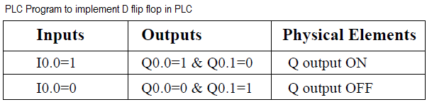
As per D flip flop, a condition of Q=1 and Q^=0 is set and a condition of Q=0 and Q^=1 is reset.
Here we can see in diagram as well as in ladder diagram, difference in D flip flop and SR flip flop is that it uses inverted value of S input.
So in D flip flop we are using only one in put for SET/RESET.
Note :- Above application may be different from actual application. This example is only for explanation purpose only. We can implement this logic in other PLC also. This is the simple concept of D flip flop.
All parameters considered in example are for explanation purpose only, parameters may be different in actual applications.
Result
Author: Bhavesh
If you liked this article, then please subscribe to our YouTube Channel for PLC and SCADA video tutorials.
You can also follow us on Facebook and Twitter to receive daily updates.
Read Next:
- Permissive and Interlock Circuits
- PLC Program Conveyor Motor
- SCADA Interview Questions
- Motor Control Circuits
- PLC Programming languages


Hi there! any idea why we can’t download this pdf? I have the same issue and to the other plc tutorials that you upload here…
Hi, We have small issue with latest version of Google Chrome,meanwhile please use other browsers like mozilla, opera etc. We try to solve this issue soon.
Sorry to bother you here but can you check this link please? i had asked a question about vfd drives….
Yes, You can get 380V 3 phase output using an single phase 230V Inverter.
Inverter manufacturers do not recommend VFD drives for single-phase supplies in excess of 3kW to ensure compliance with European Power Quality Standards such as BSEN 61000-3-2:2006 and BS EN 61000-3- 12:2005.
For similar reasons inverter manufacturers do not recommend drives with an output voltage that is different to the supply voltage (e.g.: 240v input, 415v output).
Thank you sir!
Thank you sir for your usefull information! Keep on the great job!