This is a PLC Program to implement 1:8 De-multiplexer.
1 to 8 Demultiplexer PLC
Problem Description
Implement 1:8 Demultiplexer in PLC using ladder diagram programming language.
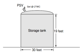
Problem Diagram

Problem Solution
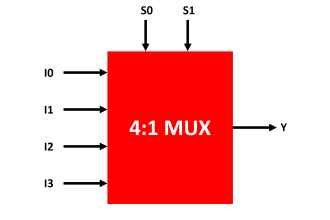
Demultiplexer has one data input Di and three select inputs S0, S1 and S3 and 8 outputs Q0.0 to Q0.7.
To select “n” outputs, we need m select lines such that 2^m = n. Depending on the output. The selection of one of the n outputs is done by the select pins.
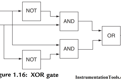
Realize the de-multiplexer using Logic Gates. Here we will configure de-multiplexer using ladder language.
When three switches are OFF and Di input is pressed then first output will be ON.As per table we can activate output by switching combination.
1:8 DeMultiplexer Truth Table

List of inputs/outputs
List of inputs
- S0 :- I0.0
- S1 :- I0.1
- S3 :- I1.0
List of outputs
- Output1 :- Q0.0
- Output 2 :- Q0.1
- Output 3 :- Q0.2
- Output 4 :- Q0.3
- Output 5 :- Q0.4
- Output 6 :- Q0.5
- Output 7 :- Q0.6
- Output 8 :- Q0.7
Ladder diagram for 1:8 Demultiplexer
Program Description
For this application, we used S7-1200 PLC and TIA portal software for programming.
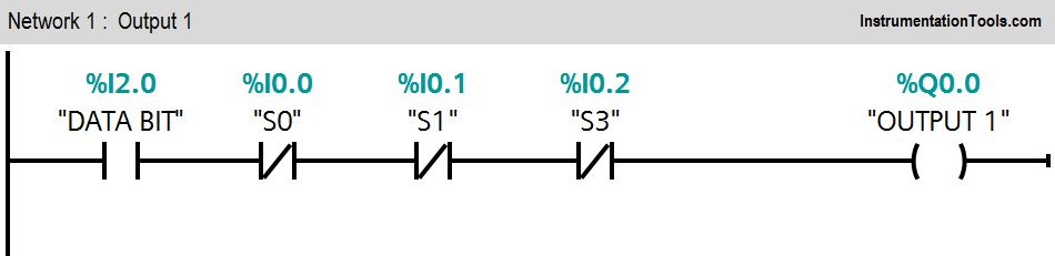
Network 1:
If Data bit (I2.0) is ON and all inputs are OFF (I0.0=0, I0.1=0 and I0.2=0), Output 1 (Q0.0) will be ON.
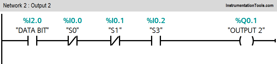
Network 2:
If data bit (I2.0) is ON, input 1 (I0.0) OFF, input 2 (I0.1) OFF and input 3 (I0.2) is ON, Output 2 (Q0.1) will be ON.
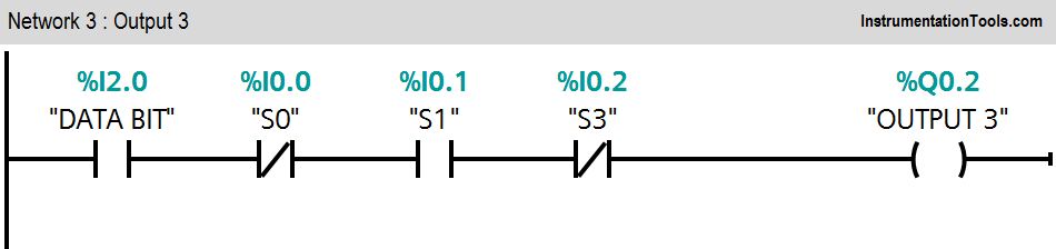
Network 3:
If data bit (I2.0) is ON, input 1 (I0.0) OFF, input 3 (I0.2) OFF and input 2 (I0.1) is ON, Output 3 (Q0.2) will be ON.
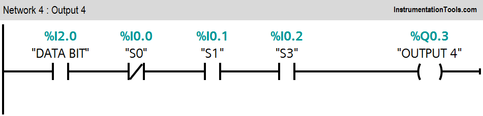
Network 4:
If data bit (I2.0) is ON, input 2 (I0.1) ON, input 3 (I0.2) ON and input 1 (I0.0) is OFF, Output 4 (Q0.3) will be ON.
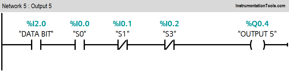
Network 5:
If input 2 (I0.1) and input 3 (I0.2) are OFF and input 1 (I0.0) is ON, Output 5 (Q0.4) will be ON.
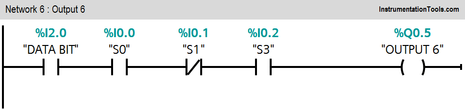
Network 6:
If data bit (I2.0) is ON, input 1 (I0.0), input 3 (I0.2) ON and input 2 (I0.1) is OFF, Output 6 (Q0.5) will be ON.
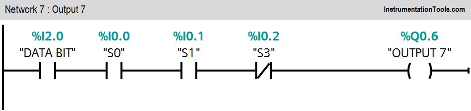
Network 7:
If data bit (I2.0) is ON, input 1 (I0.0), input 2 (I0.1) ON and input 3 (I0.2) is OFF, Output 7 (Q0.6) will be ON.
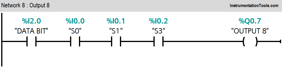
Network 8:
If data bit (I2.0) is ON, input 1 (I0.0), input 2 (I0.1) and input 3 (I0.2) ON, Output 8 (Q0.7) will be ON.
Note :- Above application may be different from actual application. This example is only for explanation purpose only. We can implement this logic in other PLC also. This is the simple concept of 1:8 Demultiplexer, we can use this concept in other examples also.
All parameters considered in example are for explanation purpose only, parameters may be different in actual applications. Also all interlocks are not considered in the application.
Author: Bhavesh
If you liked this article, then please subscribe to our YouTube Channel for PLC and SCADA video tutorials.
You can also follow us on Facebook and Twitter to receive daily updates.
Read Next:
- PLC 3 to 8 Line Decoder
- Matrix Keypad works ?
- PLC T Flip Flop Logic
- Flow Totalizer in PLC
- SR Flip Flop using PLC