Inst ToolsInst ToolsInst Tools
  • Courses
  • Automation
    • PLC
    • Control System
    • Safety System
    • Communication
    • Fire & Gas System
  • Instrumentation
    • Design
    • Pressure
    • Temperature
    • Flow
    • Level
    • Vibration
    • Analyzer
    • Control Valve
    • Switch
    • Calibration
    • Erection & Commissioning
  • Interview
    • Instrumentation
    • Electrical
    • Electronics
    • Practical
  • Q&A
    • Instrumentation
    • Control System
    • Electrical
    • Electronics
    • Analog Electronics
    • Digital Electronics
    • Power Electronics
    • Microprocessor
  • Request
Search
  • Books
  • Software
  • Projects
  • Process
  • Tools
  • Basics
  • Formula
  • Power Plant
  • Root Cause Analysis
  • Electrical Basics
  • Animation
  • Standards
  • 4-20 mA Course
  • Siemens PLC Course
Reading: How the Matrix Keypad works with a Micro controller?
Share
Font ResizerAa
Inst ToolsInst Tools
Font ResizerAa
  • Courses
  • Design
  • PLC
  • Interview
  • Control System
Search
  • Courses
  • Automation
    • PLC
    • Control System
    • Safety System
    • Communication
    • Fire & Gas System
  • Instrumentation
    • Design
    • Pressure
    • Temperature
    • Flow
    • Level
    • Vibration
    • Analyzer
    • Control Valve
    • Switch
    • Calibration
    • Erection & Commissioning
  • Interview
    • Instrumentation
    • Electrical
    • Electronics
    • Practical
  • Q&A
    • Instrumentation
    • Control System
    • Electrical
    • Electronics
    • Analog Electronics
    • Digital Electronics
    • Power Electronics
    • Microprocessor
  • Request
Follow US
All rights reserved. Reproduction in whole or in part without written permission is prohibited.
Inst Tools > Blog > Electronic Devices & Circuits > How the Matrix Keypad works with a Micro controller?

How the Matrix Keypad works with a Micro controller?

Last updated: September 27, 2016 7:52 am
Editorial Staff
Electronic Devices & Circuits
No Comments
Share
1 Min Read
SHARE

The matrix is controlled by a micro-controller.
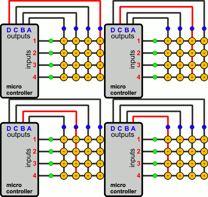
Matrix Keypad when there is no Button press

For the above 16-button 4×4 matrix, 8 pins of the micro controller will be used.

The first 4 pins will be OUTPUTS and will be connected to the COLUMN wires, while the other 4 pins will be INPUTS and will be connected to the ROW wires.

The OUTPUTS of the micro-controller will NOT all have power at the same time.

The outputs will go high one by one in cycle.

During this time, it will also monitor the inputs for a signal. As long as all inputs are LOW , the Micro-controller will take no action.

Now, suppose that the operator presses the button 3C.
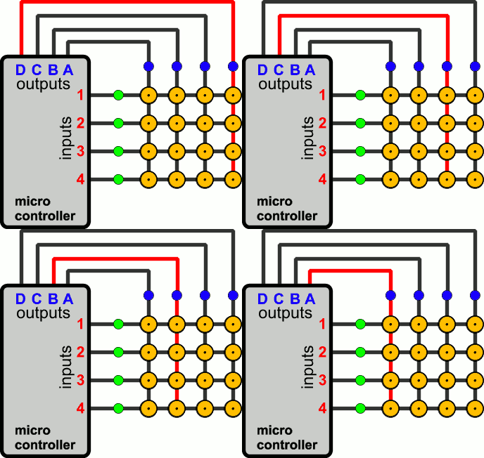
Button 3C of the Matrix Keypad is pressed

This button has connect the matrix col C, with the matrix row 3.

When the output C of the micro-controller becomes HIGH, the signal arrives also at the input 3 of the micro-controller, through the pressed button.

The micro-controller check the 4 inputs and detects that when the specific output (C) is high, there is a HIGH signal at the input 3.

So, this means that the input C3 is pressed!
Don't Miss Our Updates
Be the first to get exclusive content straight to your email.
We promise not to spam you. You can unsubscribe at any time.
Invalid email address
You've successfully subscribed !

Continue Reading

Troubleshooting a Biased Transistor
What is a Memristor? Principle, Advantages, Applications
What is Kirchhoff’s Current Law
Transistor Collector Characteristic Curves
Types of Resistors
Laser Diode Working Principle
Share This Article
Facebook Whatsapp Whatsapp LinkedIn Copy Link
Share
Leave a Comment

Leave a Reply Cancel reply

Your email address will not be published. Required fields are marked *

Stay Connected

128.3kFollowersLike
69.1kFollowersFollow
210kSubscribersSubscribe
38kFollowersFollow

Categories

Explore More

Why Silicon is preferred over Germanium ?
Basics of Ohm’s Law
Amplifiers Questions & Answers
Diodes Voltage Tripler
Short Circuit and Open Circuit
Dependent Voltage Source
Power MOSFET Safe Operating Area
Phototransistor Working Principle

Keep Learning

Transistor Biasing

Transistor Biasing

What is a Filter Circuit

What is a Filter Circuit ?

Reverse Bias Diode Working Animation

Forward Bias & Reverse Bias Diode Working Animation

Zener Diode Voltage Regulator Operation

Zener Diode Voltage Regulator Operation

pi filter Operation

pi filter Operation

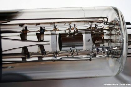
Electron Gun of CRT

Electron Gun of Cathode Ray Tube

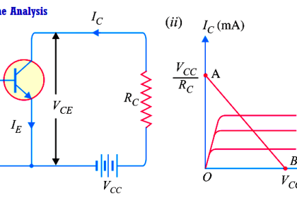
Transistor Load Line Analysis

Transistor Load Line Analysis

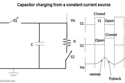
principle of time base generator

Time Base Generator

Learn More

Magnehelic Gauge Calibration

Magnehelic Gauge Calibration

Torque Measurement Objective Questions

Torque Measurement Objective Questions

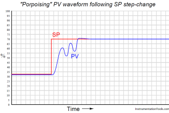
Porpoising PID Controller

Recognizing a Porpoising PID Controller

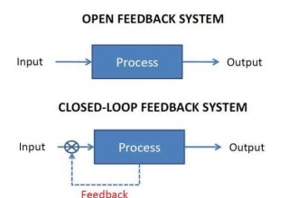
open vs closed loop

Open Loop and Closed Loop Animation

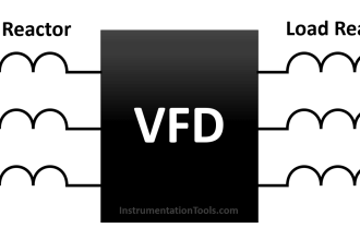
What is a Line Choke or Reactor in a VFD

What is a Line Choke or Reactor in a VFD?

S7 1200 PLC Program

Siemens S7 1200 PLC configuration in TIA Portal

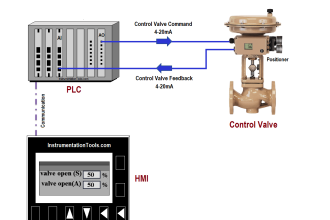
PLC Program for Control Valve Scaling

PLC Program for Control Valve Scaling

AC to DC Conversion with a Commutator

DC Machines Terminology

Menu

  • About
  • Privacy Policy
  • Copyright

Quick Links

  • Learn PLC
  • Helping Hand
  • Part Time Job

YouTube Subscribe

Follow US
All rights reserved. Reproduction in whole or in part without written permission is prohibited.
Welcome Back!

Sign in to your account

Username or Email Address
Password

Lost your password?