Inst ToolsInst ToolsInst Tools
  • Courses
  • Automation
    • PLC
    • Control System
    • Safety System
    • Communication
    • Fire & Gas System
  • Instrumentation
    • Design
    • Pressure
    • Temperature
    • Flow
    • Level
    • Vibration
    • Analyzer
    • Control Valve
    • Switch
    • Calibration
    • Erection & Commissioning
  • Interview
    • Instrumentation
    • Electrical
    • Electronics
    • Practical
  • Q&A
    • Instrumentation
    • Control System
    • Electrical
    • Electronics
    • Analog Electronics
    • Digital Electronics
    • Power Electronics
    • Microprocessor
  • Request
Search
  • Books
  • Software
  • Projects
  • Process
  • Tools
  • Basics
  • Formula
  • Power Plant
  • Root Cause Analysis
  • Electrical Basics
  • Animation
  • Standards
  • 4-20 mA Course
  • Siemens PLC Course
Reading: PLC Level Control of Two Tanks
Share
Notification Show More
Font ResizerAa
Inst ToolsInst Tools
Font ResizerAa
  • Courses
  • Design
  • PLC
  • Interview
  • Control System
Search
  • Courses
  • Automation
    • PLC
    • Control System
    • Safety System
    • Communication
    • Fire & Gas System
  • Instrumentation
    • Design
    • Pressure
    • Temperature
    • Flow
    • Level
    • Vibration
    • Analyzer
    • Control Valve
    • Switch
    • Calibration
    • Erection & Commissioning
  • Interview
    • Instrumentation
    • Electrical
    • Electronics
    • Practical
  • Q&A
    • Instrumentation
    • Control System
    • Electrical
    • Electronics
    • Analog Electronics
    • Digital Electronics
    • Power Electronics
    • Microprocessor
  • Request
Follow US
All rights reserved. Reproduction in whole or in part without written permission is prohibited.
Inst Tools > Blog > PLC Tutorials > PLC Level Control of Two Tanks

PLC Level Control of Two Tanks

Design a ladder logic for PLC level control of two tanks. Learn the PLC programming with practice problems.

Last updated: November 3, 2023 12:47 pm
Editorial Staff
PLC Tutorials
1 Comment
Share
4 Min Read
SHARE

Design a ladder logic for PLC level control of two tanks. Learn the PLC programming with practice problems.

Contents
PLC Level Control of Two TanksProblem DiagramProblem SolutionList of inputs and outputsPLC Ladder diagram for level controlling of two tanksProgram ExplanationResult

PLC Level Control of Two Tanks

Problem Description

Two simultaneous process are to be performed in two separate tanks which are connected through a valve.

First Process takes place in process tank 1 and second process takes place in tank 2. Write the ladder program for level controlling of two tanks in PLC.

Problem Diagram
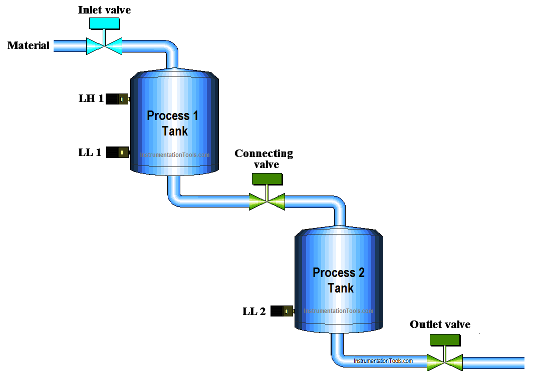
PLC Program to Control Level of Two Tanks

Problem Solution

Arrange two pressure controlled tanks for processes. Process 1 will be done in process 1 tank and process 2 will be done in process 2 tank.

Use an inlet vale for material inlet in process 1 tank. Add one more valve between two tanks as a connecting valve.

Consider two sensors (High and Low) for process 1 tank and consider only low sensor for process 2 tank.

For this application we can use PLC, we will write PLC program for this application.

List of inputs and outputs

Digital Inputs

  • Cycle START :- I0.0
  • Cycle STOP :- I0.1
  • Low level process 1 tank (LL1) :- I0.3
  • Low level process 2 tank (LL2) :- I0.4
  • High level process tank 1 (LH1) :- I0.5
  • Process 1 done :- I1.0
  • Process 2 done :- I1.1

Digital Outputs

  • Inlet valve :- Q0.0
  • Connecting valve :- Q0.1
  • Outlet Valve :- Q0.2

M memory

  • Cycle ON bit :- M0.0

PLC Ladder diagram for level controlling of two tanks

PLC Level Control of Two Tanks
PLC Level Control
Tank Level Control
PLC Tank Level

Program Explanation

For this application, we used S7-300 PLC and TIA portal software for programming. We can implement this logic by using other PLC also.

Network 1:

Network 1 is for latching circuit. Whenever START button is pressed (I0.0), Cycle ON (M0.0) bit will be ON. Cycle can be STOP by pressing STOP PB (I0.1).

Network 2:

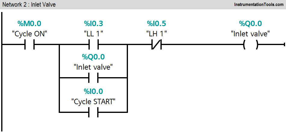
If LL1 (I0.2) is detected and cycle START is pressed, an inlet valve (Q0.0) will be ON. Consider LH 1(I0.3) interlock during this function.

Network 3:

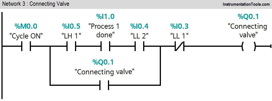
When the level of material of process tank 1 goes high hence LH 1(I0.3) is detected and level of material in process 2 tank goes low, connecting valve (Q0.1) will be ON. This function takes place while PLC is detecting process 1 done command.

Network 4:

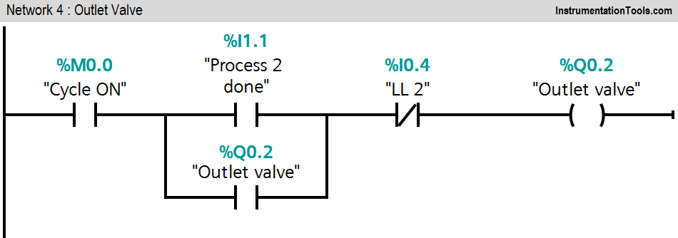
When process 2 is completed and process 2 tank is not low, an outlet valve (Q0.2) will be ON. Cycle ON bit (M0.0) should be ON during the whole cycle.

Note : The above application may be different from actual application. This example is only for explanation purpose only. We can implement this logic in other PLC also.

Result

Level Control of Two Tanks

Author: Bhavesh

If you liked this article, then please subscribe to our YouTube Channel for PLC and SCADA video tutorials.

You can also follow us on Facebook and Twitter to receive daily updates.

Read Next:

  • PLC Execution of the Application
  • VFD Motor Speed Control
  • PLC Heating and Mixing of Products
  • Two Way Switch Logic using PLC
  • PLC Counting Moving Objects
Don't Miss Our Updates
Be the first to get exclusive content straight to your email.
We promise not to spam you. You can unsubscribe at any time.
Invalid email address
You've successfully subscribed !

Continue Reading

Allen Bradley Studio 5000: Motor Running Hours PLC Program
Check Block Consistency Tools in Simatic Manager
Daily Alarm PLC Program using Real-Time Clock
What is a Line Choke or Reactor in a VFD?
Automate Batch Mixing with Repeated Cycles in Omron PLC
Speed Control of Pneumatic Cylinder (Explanation with PLC)
Share This Article
Facebook Whatsapp Whatsapp LinkedIn Copy Link
Share
1 Comment
  • Pradeep says:
    September 16, 2018 at 10:18 am

    Where is ladder diagtam for process 1&2. Please mention it, so that new comers can under easily.

    Reply

Leave a Reply Cancel reply

Your email address will not be published. Required fields are marked *

Stay Connected

128.3kFollowersLike
69.1kFollowersFollow
210kSubscribersSubscribe
38kFollowersFollow

Categories

Explore More

#11 PLC Best Practices – Instrument for Plausibility Checks
Seven Segment Display Programming with Structured Text
Readings Mismatch between Field & Control Room ? Why
How to Convert Current to Voltage using Resistor ?
Upload Option Disabled in Siemens PLC
Programmable Logic Controller Quiz
How to import GSD files into the TIA Portal? – Siemens PLC
Quiz: Identifying I/O Examples in PLC Systems

Keep Learning

memory types in siemens plc

Memory Structure of Siemens PLC

Cybersecurity in PLC

Cybersecurity in PLC

Relay Internal Parts

Relay Operation, Types, Symbols & Characteristics

Batch Mixing with PLC Ladder Logic Program

Batch Mixing with PLC Ladder Logic Program

Automation Engineer Troubleshooting Tips

Best Way to Build Troubleshooting Mindset for Automation Engineer

Siemens CP Module

Communication Processor Module in Siemens PLC

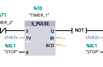
Pulse Generation using Timer in Siemens PLC

Pulse Generation using Timer in Siemens PLC

SCADA in Cloud

Cloud-Based SCADA Projects – Try Free Demo Account

Learn More

Digital Electronics Multiple Choice Questions

Half Adder and Full Adder Objective Questions

dissolved-oxygen-probe-calibration-procedure

Dissolved oxygen probe calibration procedure

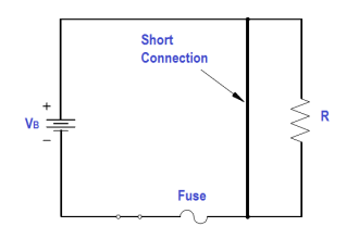
Electric Short Circuit

Series Short Circuit Faults

Control Valves - Repeat Actuator Diaphragm Bursts

Control Valves – Repeat Actuator Diaphragm Bursts

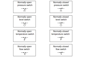
Process Switches Normal Status

Define Normal Status for each of the Process Switch

Embedded Systems

Introduction to Embedded Systems – Features, Types, Applications

Siemens LOGO PLC Complete Programming Course

Siemens LOGO PLC Complete Programming Course

VFD Commissioning and Testing Procedure

VFD Commissioning and Testing Procedure (Variable Frequency Drive)

Menu

  • About
  • Privacy Policy
  • Copyright

Quick Links

  • Learn PLC
  • Helping Hand
  • Part Time Job

YouTube Subscribe

Follow US
All rights reserved. Reproduction in whole or in part without written permission is prohibited.
Welcome Back!

Sign in to your account

Username or Email Address
Password

Lost your password?