This is a PLC Program for motor operation based on time cycle. Learn the PLC programming related to electrical engineering.
Motor Time Cycle Sequence
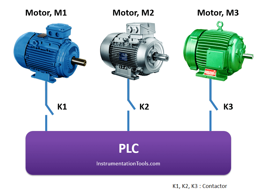
Implement the logic in PLC for motors operation based on time cycle using ladder diagram language.
Problem Diagram
Problem Solution
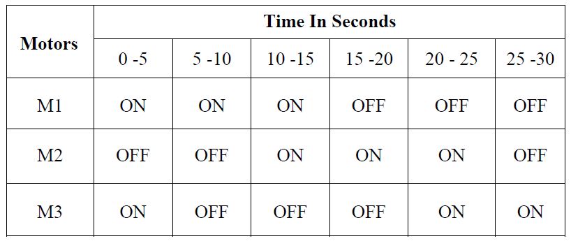
Total 3 motors are used in this logic. Each motor should run for a total of 15 seconds duration.
For the first 5 sec. time duration the previous motor should also run along with the first motor. For next 5 sec. first motor should run alone and then second motor should be ON for next 15 sec.
The ON/OFF sequence of all three motors should be as per table given below. The sequence should continue till start input is present. When start input is switched OFF the sequence should stop.
Motors ON/OFF Sequence Table
List of inputs/outputs
List of inputs
- START PB :- I0.0
- STOP PB :- I0.1
List of outputs
- Motor 1(M1) :- Q0.0
- Motor 2(M2) :- Q0.1
- Motor 3(M3) :- Q0.2
M memory
- Cycle ON :- M0.0
- Relay coil :- M10.0
PLC Program for motors operation based on a time cycle


Program Description
For this application we used S7-300 PLC and TIA portal software for programming.
Network 1:
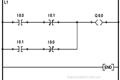
Cycle can be started by pressing START PB (I0.0) and can be stopped by pressing STOP PB (I0.1).M0.0 is cycle ON bit.
Network 2:
When cycle is ON, Main timer of 30s will start. Timer will turn OFF automatically after 30 sec by its own output (DB3.DBX6.0) or we can use relay coil (M10.0).
Network 3:
If main actual time is less or equal than 15sec, motor 1 (Q0.0) will remain ON.
Network 4:
If actual time is greater or equal than 10 sec and less or equal than 25sec, motor 2 (Q0.1) will remain ON.
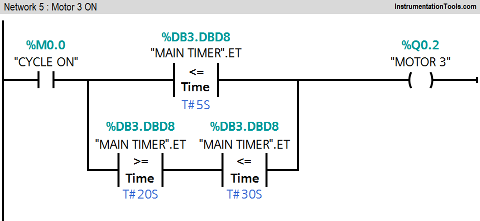
Network 5:
If actual time is either less or equal 5sec or between 20sec and 30ses, motor 3 (Q0.2) will remain ON
Note :- Above application may be different from actual application. This example is only for explanation purpose only. We can implement this logic in other PLC also. This is simple concept of motor operation on given time cycle, we can use this concept in other examples also.
All parameters considered in example are for explanation purpose only, parameters may be different in actual applications. Also all interlocks are not considered in the application.
Result

If you liked this article, then please subscribe to our YouTube Channel for PLC and SCADA video tutorials.
You can also follow us on Facebook and Twitter to receive daily updates.
Read Next:
- Raw Counts to Engineering Units
- Motor Operation from Local Control Panel
- PLC Application for Stamping Operation
- Web-based SCADA HMI Software
- Setpoints and Alarms in Control System



Dear Author,
Kindly make your PLC programs in PLC S7 300 & S7 400 programming format, as most of the programs that you are showing are in S7 1200 format. I kindly request you to do the same or if you have already do then kindly let me know please. As most of the people dont have TIA portal for S7 1200.
Thanks & Regards
Mohammad Mobin