Inst ToolsInst ToolsInst Tools
  • Courses
  • Automation
    • PLC
    • Control System
    • Safety System
    • Communication
    • Fire & Gas System
  • Instrumentation
    • Design
    • Pressure
    • Temperature
    • Flow
    • Level
    • Vibration
    • Analyzer
    • Control Valve
    • Switch
    • Calibration
    • Erection & Commissioning
  • Interview
    • Instrumentation
    • Electrical
    • Electronics
    • Practical
  • Q&A
    • Instrumentation
    • Control System
    • Electrical
    • Electronics
    • Analog Electronics
    • Digital Electronics
    • Power Electronics
    • Microprocessor
  • Request
Search
  • Books
  • Software
  • Projects
  • Process
  • Tools
  • Basics
  • Formula
  • Power Plant
  • Root Cause Analysis
  • Electrical Basics
  • Animation
  • Standards
  • 4-20 mA Course
  • Siemens PLC Course
Reading: PLC Timer Programming Examples – TON, TOF, TP and TONR
Share
Font ResizerAa
Inst ToolsInst Tools
Font ResizerAa
  • Courses
  • Design
  • PLC
  • Interview
  • Control System
Search
  • Courses
  • Automation
    • PLC
    • Control System
    • Safety System
    • Communication
    • Fire & Gas System
  • Instrumentation
    • Design
    • Pressure
    • Temperature
    • Flow
    • Level
    • Vibration
    • Analyzer
    • Control Valve
    • Switch
    • Calibration
    • Erection & Commissioning
  • Interview
    • Instrumentation
    • Electrical
    • Electronics
    • Practical
  • Q&A
    • Instrumentation
    • Control System
    • Electrical
    • Electronics
    • Analog Electronics
    • Digital Electronics
    • Power Electronics
    • Microprocessor
  • Request
Follow US
All rights reserved. Reproduction in whole or in part without written permission is prohibited.
Inst Tools > Blog > PLC Tutorials > PLC Timer Programming Examples – TON, TOF, TP and TONR

PLC Timer Programming Examples – TON, TOF, TP and TONR

Discuss about PLC Timer Programming Examples - Different PLC Timers are TON, TOF, TP, and TONR. PLC Timer Instructions and Timer logics.

Last updated: November 1, 2023 2:49 pm
Editorial Staff
PLC Tutorials
2 Comments
Share
7 Min Read
SHARE

Discuss about PLC Timer Programming Examples: Different PLC Timers are TON, TOF, TP, and TONR. PLC Timer Instructions and PLC Timer logic examples.

Contents
PLC Timer ProgrammingProblem DiagramProblem SolutionList of Inputs/OutputsPLC Ladder diagram for TimersRuntime Test Cases

PLC Timer Programming

Implementation of IEC timers (TON, TOF, TP &TONR) in S7-1200 PLC using TIA Portal.

In many applications, there is a requirement to control time or signal flow. For example, a valve, or a motor might need to be controlled to operate for a particular interval of time, switched ON after some time interval or after some delay.

Problem Diagram

PLC Timer Programming
PLC IEC Timers

Problem Solution

For this problem, we will use IEC timers (TON, TOF, TP &TONR) in S7-1200 PLC with examples.

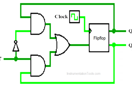
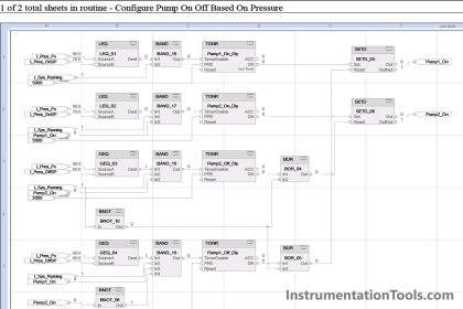
There are a number of different forms of timers that can be found in PLCs. As shown in the above diagram,

  • ON delay timer which becomes ON after a particular time delay.
  • Off delay timers are ON for a fixed period of time after turning OFF input.
  • Pulse timer switches ON or OFF for a fixed period of time.
  • Accumulator timer is which records time intervals.

Here consider the example of four motors and four SWITCHES for an explanation of timers. We need to start three motors in different ways.

  1. The first motor will start after a 10 sec delay,
  2. the second motor will start immediately and off after a 10 sec delay and
  3. the third motor will start with a pulse and off with a 10-second delay.
  4. The fourth motor will run for a total of 10 sec.

List of Inputs/Outputs

Inputs List

  • SWITCH 1: I0.0
  • SWITCH 2: I0.1
  • SWITCH 3: I0.2
  • SWITCH 4: I0.3
  • Reset: I0.4

Outputs List

  • MOTOR 1: Q0.0
  • MOTOR 2: Q0.1
  • MOTOR 3: Q0.2
  • MOTOR 4: Q0.3

PLC Ladder diagram for Timers

We can use the Generate-ON-delay or ON delay timer instruction to delay the setting of the Q output by the programmed duration PT. The instruction is started when the result of the input IN changes from 0 to 1 (positive edge).

You can monitor the current time value at the ET output of the Timer block. The timer value starts at T#0s and ends when the value of duration PT is reached. The ET output is reset as soon as the signal state at the IN input changes to 0.

PLC ON Delay Timer

We can use the Generate off-delay or off-delay timer instruction to delay resetting of the Q output by the programmed duration PT.

The Q output is set when the result of the logic operation (RLO) at input IN changes from 0 to 1 (positive signal edge).

We can monitor the current time value at the ET output.

PLC OFF Delay Timer

We can use the Generate pulse instruction to set the output Q for a programmed duration.

The instruction is started when the result of the input IN changes from 0 to 1 (positive edge).

Programmed time (PT) begins when the instruction starts. In this timer even if a new positive edge is detected, the signal state at the output Q is not affected as long as the PT time duration is running.

PLC Pulse Timer

The Time accumulator instruction or accumulator timer is used to accumulate time values within a period set by the programmed time (PT) parameter.

When the signal state at input IN changes from 0 to 1 (positive edge), the instruction is executed, and the duration PT starts.

In this case, the Q parameter remains set to 1, even when the signal state at the IN parameter changes from 1 to 0″(negative edge). The R input resets the output Q.

PLC Accumulator Timer

Program Description

In this problem we will consider S7-1200 PLC and TIA portal software for programming.

Network 1:

In this network we have used ON delay timer (generate on delay) for MOTOR 1(Q0.0).

When the status of the SWITCH 1(I0.0) changes from 0 to 1 the timer instruction will be executed and it will activate the MOTOR 1(Q0.0) after 10s delay.

Network 2:

In this network we have used off delay timer (generate off delay) for MOTOR 2(Q0.1).

When the status of the SWITCH 2(I0.1) changes from 0 to 1 the timer instruction will be executed and it will activate the MOTOR 2(Q0.1) immediately.

Also when the SWITCH 2(I0.1) status changes back to 0 then programmed time (PT) will start and after time MOTOR 2(Q0.1) will be OFF.

Network 3:

In this network we have used pulse timer (generate pulse) for MOTOR 3(Q0.2).

When the status of the SWITCH 3(I0.2) changes from 0 to 1 the timer instruction will be executed and it will activate the MOTOR 3(Q0.2) immediately.

In this case even new positive edge is detected, the status of the MOTOR 3(Q0.2) is not affected as long as programmed time (PT) is running.

Network 4:

In this network we have used accumulator timer (accumulator time) for MOTOR 4(Q0.3).When the status of the SWITCH 4(I0.3) changes from 0 to 1 the timer instruction will be executed and MOTOR 4(Q0.3) will start after 10s.

The MOTOR 4(Q0.2) will remain ON, even when the input status changes back to 0.The Reset (I0.4) is necessary to reset the timer or accumulated time.

Runtime Test Cases

PLC Timers Example

PLC Programming Tutorial for Beginners - Siemens PLC Training Course

Author: Bhavesh

If you liked this article, then please subscribe to our YouTube Channel for PLC and SCADA video tutorials.

You can also follow us on Facebook and Twitter to receive daily updates.

Read Next:

  • Alarm and Trip Systems
  • Allen Bradley PLC Programming
  • PLC Input and Output Modules
  • Analog Input Conversion Formula
  • Car Parking PLC Progam
Don't Miss Our Updates
Be the first to get exclusive content straight to your email.
We promise not to spam you. You can unsubscribe at any time.
Invalid email address
You've successfully subscribed !

Continue Reading

PLC Programmer Salary and Future Career Scope
Design a Program Using Studio 5000 and FactoryTalk View Studio
SCADA Multiple Choice Questions
PLC Program for Automatic Liquid Mixing Application
Jump Instruction in Siemens Tia Portal
Features of SCADA
Share This Article
Facebook Whatsapp Whatsapp LinkedIn Copy Link
Share
2 Comments
  • Kumar says:
    March 23, 2024 at 2:59 pm

    Thank you very much dear sir for your efforts

    Reply
  • Ray says:
    July 14, 2024 at 2:47 am

    Thank you sir.

    Reply

Leave a Reply Cancel reply

Your email address will not be published. Required fields are marked *

Stay Connected

128.3kFollowersLike
69.1kFollowersFollow
210kSubscribersSubscribe
38kFollowersFollow

Categories

Explore More

Delta PLC Counter with Comparison
Electrical Switches Principle & Types
PLC Program to Drain Same Products from Two Tanks
Siemens PLC Tia Portal – OB100 Start-up Organization Block
Procedure for Reading or Searching the Tag number in Siemens PLC
Introduction to SCADA
PLC Input Output Modules
Introducing PLC Programming using LogixPro Simulator Software

Keep Learning

PLC Program for Controlling Conveyors ON Sequence and OFF Sequence

PLC Program – Controls Conveyors ON and OFF Sequence

PLC Compressor Control Ladder Logic

PLC Compressor Control Ladder Logic

Control Speed of an Induction Motor using Analog Output of PLC

Control Speed of Induction Motor using Analog Output of PLC

DCS Marshalling Cabinet

The Purpose of Marshalling Cabinet or Marshalling Panel

Machine Tool and Coolant Control PLC Ladder Logic

Machine Tool and Coolant Control: PLC Ladder Logic Design

factorytalk view studio hmi

How to Create Templates in FactoryTalk View Studio?

Structured Text PLC Example for Motor Interlocking and Control

Structured Text PLC Example for Motor Interlocking and Control

PLC Program for Forward and Reverse Motor control

3 Phase Motor Control using PLC Ladder Logic

Learn More

Rotary Granulator Drive

Rotary Granulator Drive Root Cause Analysis (RCA)

Sprocket Assembly and Bolting Segments

Bucket elevators Chain and teeth wear Problems

Area Velocity Flow Meter Principle

Area Velocity Flow Meter Principle

Start the Counting from a Preset Value in PLC

Start the Counting from a Preset Value in PLC

PLC Commissioning and Testing

PLC Commissioning and Testing Procedure (Programmable Logic Controller)

Gas Suppression System

What is Gas Suppression Systems ?

Internet of Things (IOT)

History of Internet of Things (IOT)

Siemens Profibus Interface DP

How to Create New Project Using Simatic Manager

Menu

  • About
  • Privacy Policy
  • Copyright

Quick Links

  • Learn PLC
  • Helping Hand
  • Part Time Job

YouTube Subscribe

Follow US
All rights reserved. Reproduction in whole or in part without written permission is prohibited.
Welcome Back!

Sign in to your account

Username or Email Address
Password

Lost your password?