This is a PLC Program to implement analog scaling in S7-300 PLC.
Control Valve Scaling
Problem Description
Implement PLC program in S7-300 for analog scaling.
Problem Diagram

Problem Solution
Analog inputs come from different sensors or transmitters. Transmitters convert physical quantity into electrical signal. We can measure many physical quantity by using analog sensors such as temperature, pressure, level, distance, flow etc.
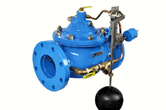
Of course we can measure all physical quantity by using analog sensors, but for example and explanation purpose here we take one example of control valve.
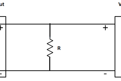
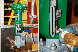
As shown in figure, here we consider one control valve and it has 4-20mA output (valve feedback) and 4-20mA input (valve command) for operation. Hence, when PLC will give 20mA to flow control valve, valve will be open 100% and for 4mA it will be 0% (close).
In other way flow control valve is also providing output signal that can be used for close loop system/for valve percentage indication. If valve is 100% open, PLC will get 20mA signal and for 0% it will get 4mA.
Note:- We consider here close loop system for simple explanation, so operator will set control valve open command parameter in range between 0% to 100% .

Now as per close loop system, control valve will provide output signal (valve feedback) and by using SCALE instruction, operator can see actual valve open parameter on graphics.

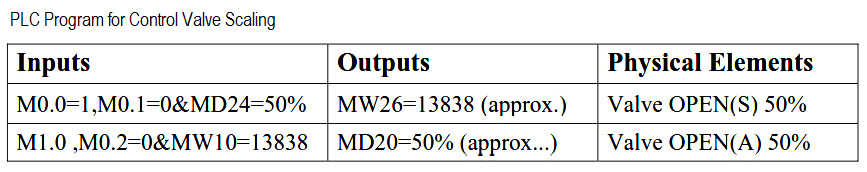
List of inputs/outputs
M memory
- Enable command-Scaling :- M0.0
- Bipolar selection-Scaling :- M0.1
- Actual value from the sensor or transmitter :- MW10
- Error word –Scaling :- MW12
- Scaled output :- MD20
- Enable command-Unscaling :- M1.0
- Bipolar selection- Unscaling :- M0.2
- Given value from the display :- MD24
- Error word-Unscaling :- MW16
- Unscaled output :- MW26
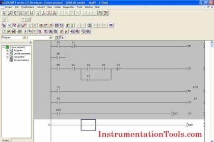
PLC Ladder Diagram for Valve Scaling

Ladder Logic Explained
For this application, we use S7-300 PLC and TIA portal software for programming. We can implement this logic by using other PLC also.
Network 1:
In this network, scaling logic is executed when Enable command (M0.0) is ON.
The “Scale” instruction is to convert the integer (here 4-20mA signal from the control valve or MW10) at the IN parameter which can be scaled in physical units between a low limit (0% output) and a high limit (100% output).
The result or scaled output (MD20) of the instruction is output at the OUT parameter.
If bipolar selection (M0.1) is ON, it is assumed that the value at the IN parameter is bipolar (range between -27648 to +27648).
If bipolar selection (M0.1) is OFF, it is assumed that the value at the IN parameter is unipolar (range between 0 to 27648).
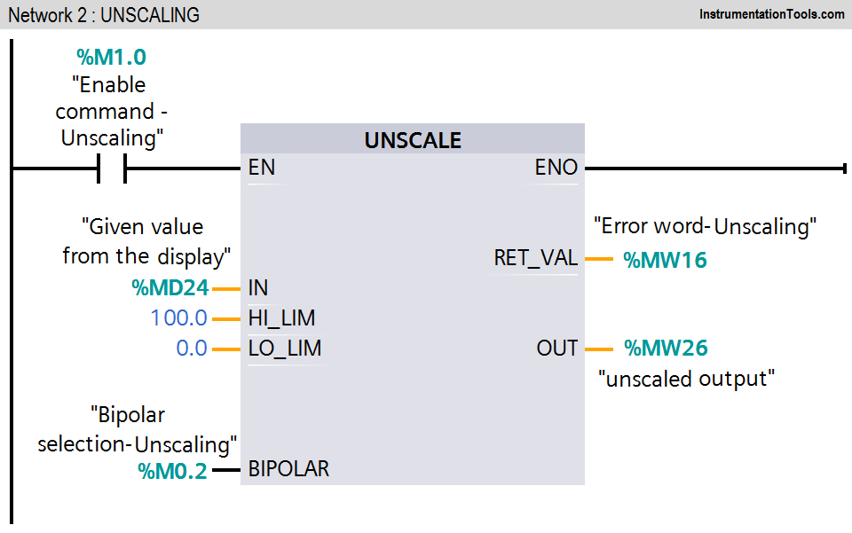
Network 2:
The “Unscale” instruction is used to unscaled the floating-point number (given value from the display or MD24) on the IN parameter into physical units between a low limit and and a high limit.
The result of the instruction is output (unscaled output MW26) at the OUT parameter. If bipolar selection (M0.2) is ON, it is assumed that the value at the IN parameter is bipolar (range between -27648 to +27648).
If bipolar selection (M0.2) is OFF, it is assumed that the value at the IN parameter is unipolar (range between 0 to 27648).
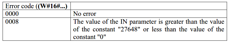
Error code table:
Note: The above application may be different from actual application. This example is only for explanation purpose only. We can implement this logic in other PLC also. This is the simple concept of SCALE and UNSCALE instructions, we can use this concept in other examples also.
All parameters considered in the example are for explanation purposes only, parameters may be different in actual applications.
Result
Author : Bhavesh
If you liked this article, then please subscribe to our YouTube Channel for PLC and SCADA video tutorials.
You can also follow us on Facebook and Twitter to receive daily updates.
Read Next:
- Sensor Scaling in PLC
- Latching Function in PLC
- PLC Ladder Diagrams
- Multiple Outputs using PLC
- PLC Continuous Filling Operation


how about a similar article like this using the SCP instruction of Allen Bradley thanks nice work here
It is important to explain where you get the range values of +27648 to -27648.
Great
Please upload types and makes PLC with photos, IO card to different types of field instruments and identification of errors in PLC