Inst ToolsInst ToolsInst Tools
  • Courses
  • Automation
    • PLC
    • Control System
    • Safety System
    • Communication
    • Fire & Gas System
  • Instrumentation
    • Design
    • Pressure
    • Temperature
    • Flow
    • Level
    • Vibration
    • Analyzer
    • Control Valve
    • Switch
    • Calibration
    • Erection & Commissioning
  • Interview
    • Instrumentation
    • Electrical
    • Electronics
    • Practical
  • Q&A
    • Instrumentation
    • Control System
    • Electrical
    • Electronics
    • Analog Electronics
    • Digital Electronics
    • Power Electronics
    • Microprocessor
  • Request
Search
  • Books
  • Software
  • Projects
  • Process
  • Tools
  • Basics
  • Formula
  • Power Plant
  • Root Cause Analysis
  • Electrical Basics
  • Animation
  • Standards
  • 4-20 mA Course
  • Siemens PLC Course
Reading: PLC Conveyor Motor Ladder Logic
Share
Font ResizerAa
Inst ToolsInst Tools
Font ResizerAa
  • Courses
  • Design
  • PLC
  • Interview
  • Control System
Search
  • Courses
  • Automation
    • PLC
    • Control System
    • Safety System
    • Communication
    • Fire & Gas System
  • Instrumentation
    • Design
    • Pressure
    • Temperature
    • Flow
    • Level
    • Vibration
    • Analyzer
    • Control Valve
    • Switch
    • Calibration
    • Erection & Commissioning
  • Interview
    • Instrumentation
    • Electrical
    • Electronics
    • Practical
  • Q&A
    • Instrumentation
    • Control System
    • Electrical
    • Electronics
    • Analog Electronics
    • Digital Electronics
    • Power Electronics
    • Microprocessor
  • Request
Follow US
All rights reserved. Reproduction in whole or in part without written permission is prohibited.
Inst Tools > Blog > PLC Tutorials > PLC Conveyor Motor Ladder Logic

PLC Conveyor Motor Ladder Logic

PLC Programming Tutorials for PLC Conveyor Motor Ladder Logic or Conveyor Belt Control using the programmable logic controller (PLC).

Last updated: November 2, 2023 4:37 pm
Editorial Staff
PLC Tutorials
4 Comments
Share
2 Min Read
SHARE

PLC Programming Tutorials for PLC Conveyor Motor Ladder Logic or Conveyor Belt Control using a programmable logic controller (PLC).

Contents
PLC Conveyor Motor Ladder LogicObjective: The sequential tasks as followsRelay SchematicOperational SequencePLC Ladder Logic

PLC Conveyor Motor Ladder Logic

PLC Program for Conveyor Motor

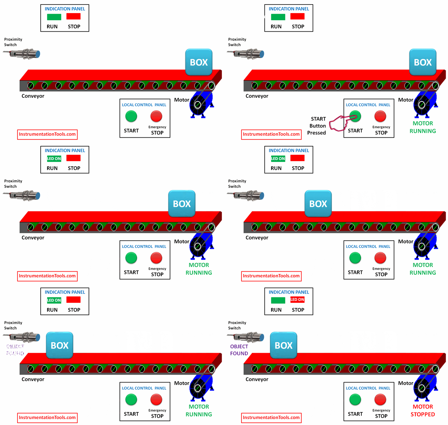
Objective: The sequential tasks as follows

  1. When START button pressed
  2. Motor will be started
  3. RUN (Green Lamp) indication lamp will be activated
  4. Motor Running, so Box will start Move
  5. Proximity Sensor will detect when the box arrives at other end
  6. Motor will be stopped
  7. RUN (Green Lamp) indication lamp will be de-activated
  8. STOP (Red Lamp) indication lamp will be activated
  9. An Emergency Stop push button will be used to stop the motor at any time.

Relay Schematic
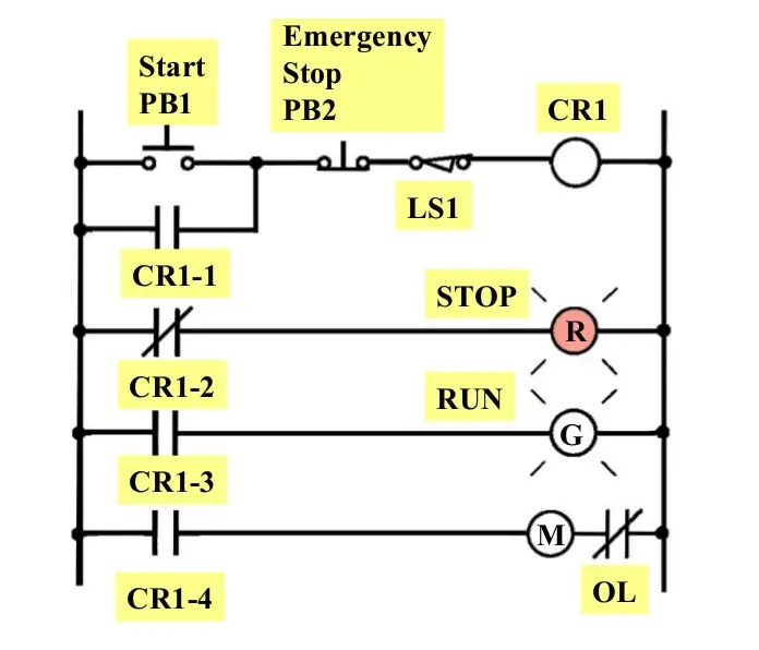
Conveyor Relay Logic
  • R : STOP Indication lamp,
  • G : RUN Indication lamp,
  • M : Motor,
  • OL : Overload Relay (Motor Protection Relay),
  • LS1 : Proximity Switch,
  • PB1 : Start push button,
  • PB2 : Emergency Stop Pushbutton,
  • CR : Contractor Relay

Operational Sequence

  • Start button is actuated.
  • CR1-1 closes to seal in CR1 or to latch the start command
  • CR1-2 opens, switching the red stop pilot light off
  • CR1-3 closes, switching the green run pilot light on
  • CR1-4 closes to energize the motor starter and motor
  • The box/package moves, and proximity switch (LS1) detects the box when it reached and de-energize coil CR1
  • CR1-1 opens to open the seal-in contact ( unlatched start command)
  • CR1-2 closes, switching the red pilot light on
  • CR1-3 opens, switching the green pilot light off
  • CR1-4 opens to de-energize the starter coil, stop the motor, and end the sequence

PLC Ladder Logic
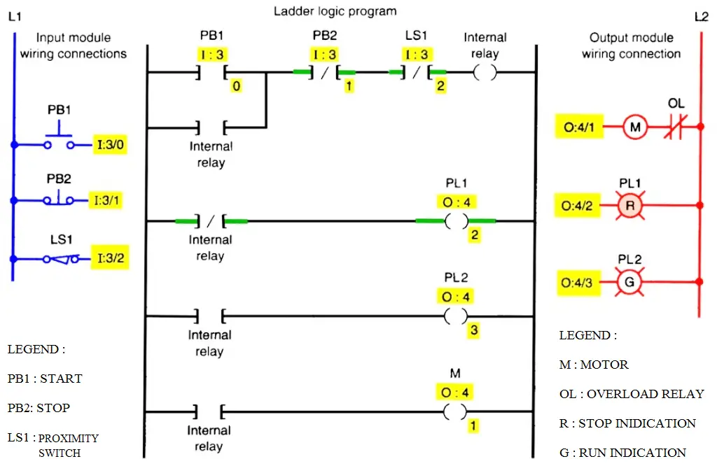
Conveyor Belt Control using PLC

If you liked this article, then please subscribe to our YouTube Channel for PLC and SCADA video tutorials.

You can also follow us on Facebook and Twitter to receive daily updates.

Read Next:

  • PLC Analog I/O and Network I/O
  • What is Ladder Diagram Programming?
  • Example of PLC Counters Program
  • PLC Energize or De-energize the Outputs
  • Two Way Switch Logic using PLC
Don't Miss Our Updates
Be the first to get exclusive content straight to your email.
We promise not to spam you. You can unsubscribe at any time.
Invalid email address
You've successfully subscribed !

Continue Reading

Series Tanks Level Control using PLC Ladder Programming
Introduction to Functional Block Diagram in Studio 5000
How to Operate a Group of Induction Motors using PLC Logic?
Free Industrial Control System (ICS) Cyber Security Training Course
What is PID Controller?
Flexible Input Output Modules
Share This Article
Facebook Whatsapp Whatsapp LinkedIn Copy Link
Share
4 Comments
  • Syed Roshan ZAMEER says:
    March 15, 2020 at 6:50 pm

    Very nice

    Reply
  • Arnel says:
    May 5, 2022 at 6:06 am

    Start-stop motor control relay logic circuit.
    By pressing start button coil relay for magnetic contactor (CR1) and green lamp energized (G). By pressing stop, it will de-energized the coil relay for magnetic contactor (CR1) and the red lamp will ON (R).
    Please convert Relay Logic Circuit into PLC Logic Circuit through complete connection and details below by using the given inputs/outputs based on the given relay logic diagram.
    (INPUT) Stop – I:0.0 , Start – I:0.1
    (OUTPUT) CR1 – O:0.0 , G – O:-0.1 , R – O:0.2

    Reply
  • Dr A.A Stephen says:
    August 29, 2022 at 8:41 am

    Good Morning editorial team please kindly permit me the use of the PLC conveyor Motor ladder logic and Relay schematic in a Journal Article am working on with my HE student and Co-lecturer .

    Hope to hear from you

    Kind Regards

    Reply
  • lokesh says:
    December 19, 2024 at 3:48 pm

    Design PLC ladder diagram for conveyor choosing system.

    An operator should be able to operate the system in the manual mode using four push button on switches and a common off switch.. The company is producing four different types of products which are categorized in blue, green, yellow and red colors for identification. These products are to be transported through different conveyors for further process.

    In the four output signals to control the system, only one output signal is supposed to be on at a time. If the operator tries to switch conveyor, the previous output should go OFF and the chosen conveyor output should be turned on.

    Reply

Leave a Reply Cancel reply

Your email address will not be published. Required fields are marked *

Stay Connected

128.3kFollowersLike
69.1kFollowersFollow
210kSubscribersSubscribe
38kFollowersFollow

Categories

Explore More

Structured Text in PLC: Parking Information Systems
Example of Controlling the PLC Output using Push Buttons
PLC FBD Programming for Burglar Alarm Security System
Animation of Electromagnetic Relay
Siemens PLC Comparator Logic
What are User Defined Function Blocks in PLC?
What is Marshalling Cabinet?
How to Use Encode and Decode Instructions in PLC ?

Keep Learning

PID Setup

PID in Studio 5000

Remote Factory Acceptance Test

Remote Factory Acceptance Test

What is a Floating License - Automation Software Systems

What is a Floating License? – Automation Software Systems

PLC Program for Temperature Control using Thermostat

PLC Program for Temperature Control using Thermostat

PLC Load Memory

What is Resources Tab in the Siemens PLC?

Conveyor Sorting Machine PLC Program

Conveyor Sorting Machine PLC Program with Calculation Function

PLC Program using Logic GATEs

PLC Logic GATE Program

What is Fail-safe in Siemens PLC?

What is Fail-safe in Siemens PLC?

Learn More

Ultrasonic Flowmeters Principle

Factors Affecting the Performance of Ultrasonic Flow Meters

Electrical Machines Questions and Answers

Measurement of Xd and Xq – Synchronous Machine

Load Cell Assembly

Urea Bagging Plant – Process Flow

Fieldbus Segment

Basics of Foundation Fieldbus

Power Electronics Objective Questions

Single Phase Voltage Source Inverter Quiz

Digital Electronics Multiple Choice Questions

Programmable Read Only Memory Objective Questions – Part 1

Single-element drum level control system

Single Element Drum Level Control System

Circuit Control Devices Multiple Choice Questions

Circuit Control Devices Multiple Choice Questions & Answers

Menu

  • About
  • Privacy Policy
  • Copyright

Quick Links

  • Learn PLC
  • Helping Hand
  • Part Time Job

YouTube Subscribe

Follow US
All rights reserved. Reproduction in whole or in part without written permission is prohibited.
Welcome Back!

Sign in to your account

Username or Email Address
Password

Lost your password?