This article discusses the PLC mixing process with adjustable timer and valve control using XG-5000 PLC Software. This Batch Mixing System has 3 Processes, Liquid Filling Process, Mixing Process, and Draining Process. When the Tank is empty, Valve 1 will automatically Open. This system uses HIGH & LOW sensors to detect the liquid contents in the Tank. When the Tank is fully filled, the Mixer will rotate and the Mixing Process time parameters can be Set. Valve 2 will automatically Open when the Mixing Process is complete. The quantity of Mixing Processes that have been carried out will be counted and can be Reset.
Program Objective
The PLC logic has these buttons and the following sensors:
- The PB_START (P00000) button is used to Start the system.
- The PB_STOP (P00001) button is used to Stop the system.
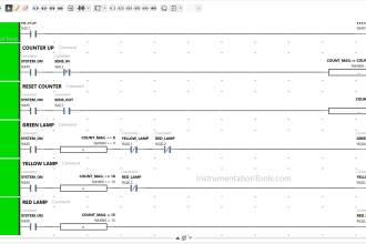
- The RESET_COUNTER (P00004) button is used to Reset the Counter value.
- The LOW_SENS (P00002) sensor is used to measure the lowest point of liquid in the tank. The sensor will be Active when it detects liquid.
- The HIGH_SENS (P00003) sensor is used to measure the highest point of liquid in the tank. The sensor will be Active when it detects liquid.
The time parameter “Set Value” for the Mixing Process in the memory word SV_TIMER_MIXER (D00010) must be Set before the system is Started.
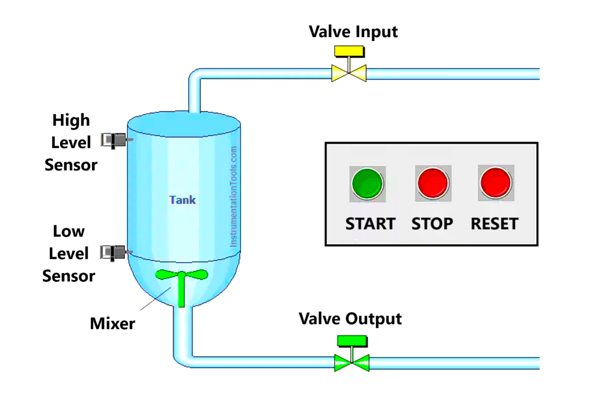
Liquid Filling Process
When the PB_START (P00000) button has been Pressed and the tank is empty, the LOW_SENS (P00002) sensor will be non-active and the Valve VALVE_INPUT (P00040) will be OPEN.
Valve VALVE_INPUT (P00040) will CLOSE when the HIGH_SENS (P00003) sensor is Active. This indicates that the liquid in the tank is full.
Mixing Process
When the Valve VALVE_INPUT (P00040) is CLOSED, the output MIXER (P00041) is to Mix the liquid.
The Mixing process will be completed when TIMER_MIXER (T0000) has finished counting and Output MIXER (P00041) becomes OFF.
Draining Process
When TIMER_MIXER (T0000) has finished counting, the Valve VALVE_OUT (P00042) will OPEN to drain the liquid from Tank.
Valve VALVE_OUT (P00042) will CLOSE again when the LOW_SENS (P00002) sensor is non-active.
When the entire process has been carried out, the Counter value in the memory word COUNTER_BATCH (D00000) will increase (+1).
Addressing of Project
| Comment | Input (I) | Output (Q) | Memory Word | Memory Bits | Timer |
| PB_START | P00000 | ||||
| PB_STOP | P00001 | ||||
| LOW_SENS | P00002 | ||||
| HIGH_SENS | P00003 | ||||
| RESET_COUNTER | P00004 | ||||
| VALVE_INPUT | P00040 | ||||
| MIXER | P00041 | ||||
| VALVE_OUT | P00042 | ||||
| SYSTEM_ON | M00000 | ||||
| TIMER_MIXER | T0000 | ||||
| COUNTER_BATCH | D00000 | ||||
| SV_TIMER_MIXER | D00010 |
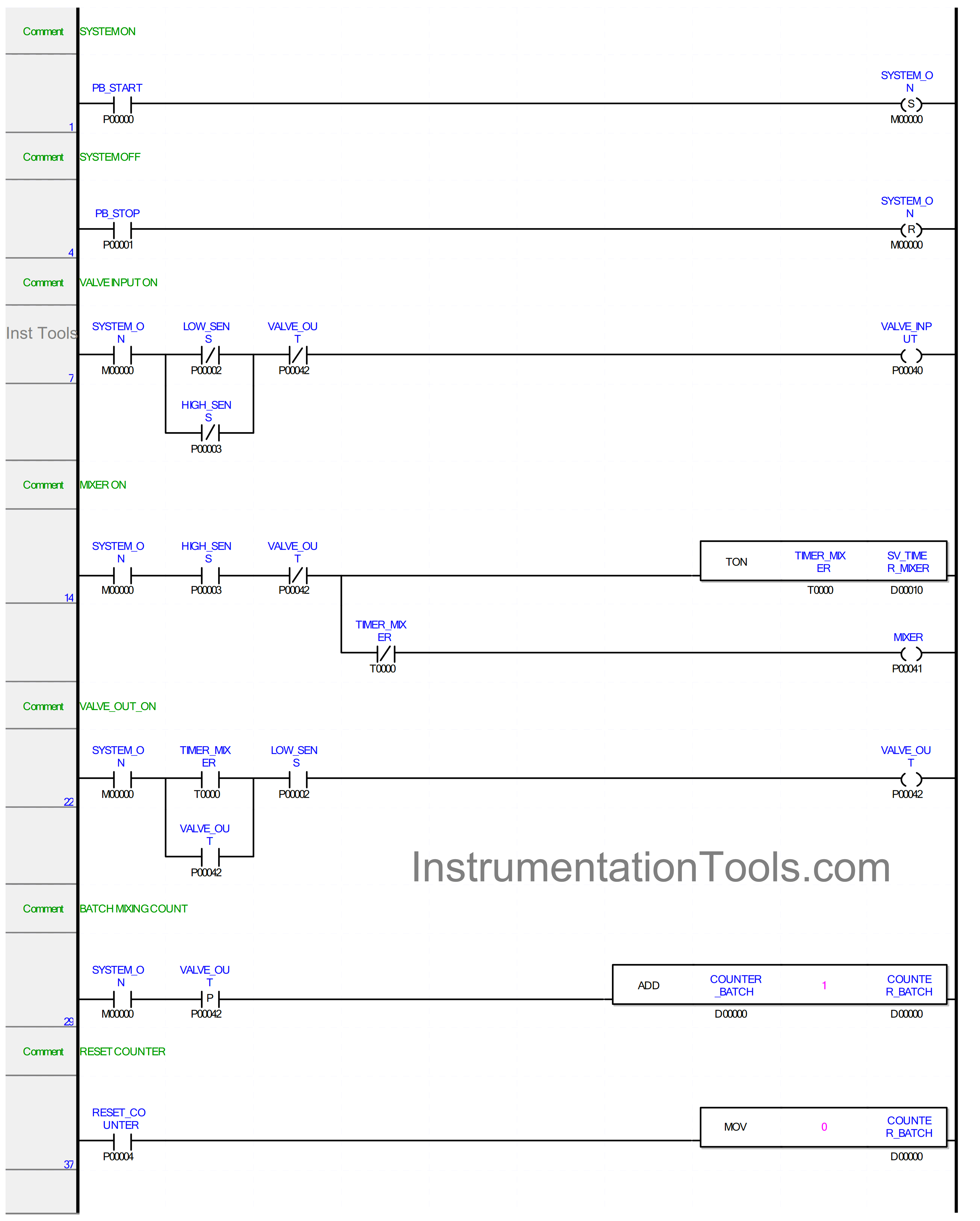
Programming of PLC Code
RUNG 1
In this Rung, when the PB_START (P00000) button is Pressed, the memory bit SYSTEM_ON (M00000) will be in the HIGH state. Because it uses the SET Coil Instruction, the memory bit SYSTEM_ON (M00000) will remain in the HIGH state even though the PB_START (P00000) button has been Released.
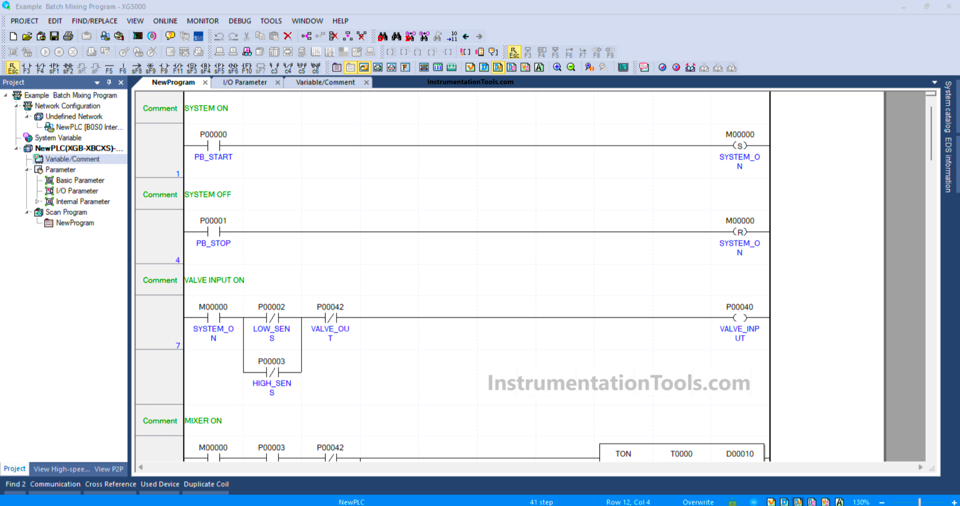
RUNG 4
Because it uses the RESET Coil Instruction, the memory bit SYSTEM_ON (M00000) will be in the LOW state if the PB_STOP (P00001) button is Pressed.
RUNG 7
In this Rung, the Output VALVE_INPUT (P00040) will be OPEN if the NO contact of memory bit SYSTEM_ON (M00000) is in the HIGH state. The VALVE_INPUT (P00040) output will be CLOSE when the NC contact of LOW_SENS (P00002) or HIGH_SENS (P00003) in the HIGH state.
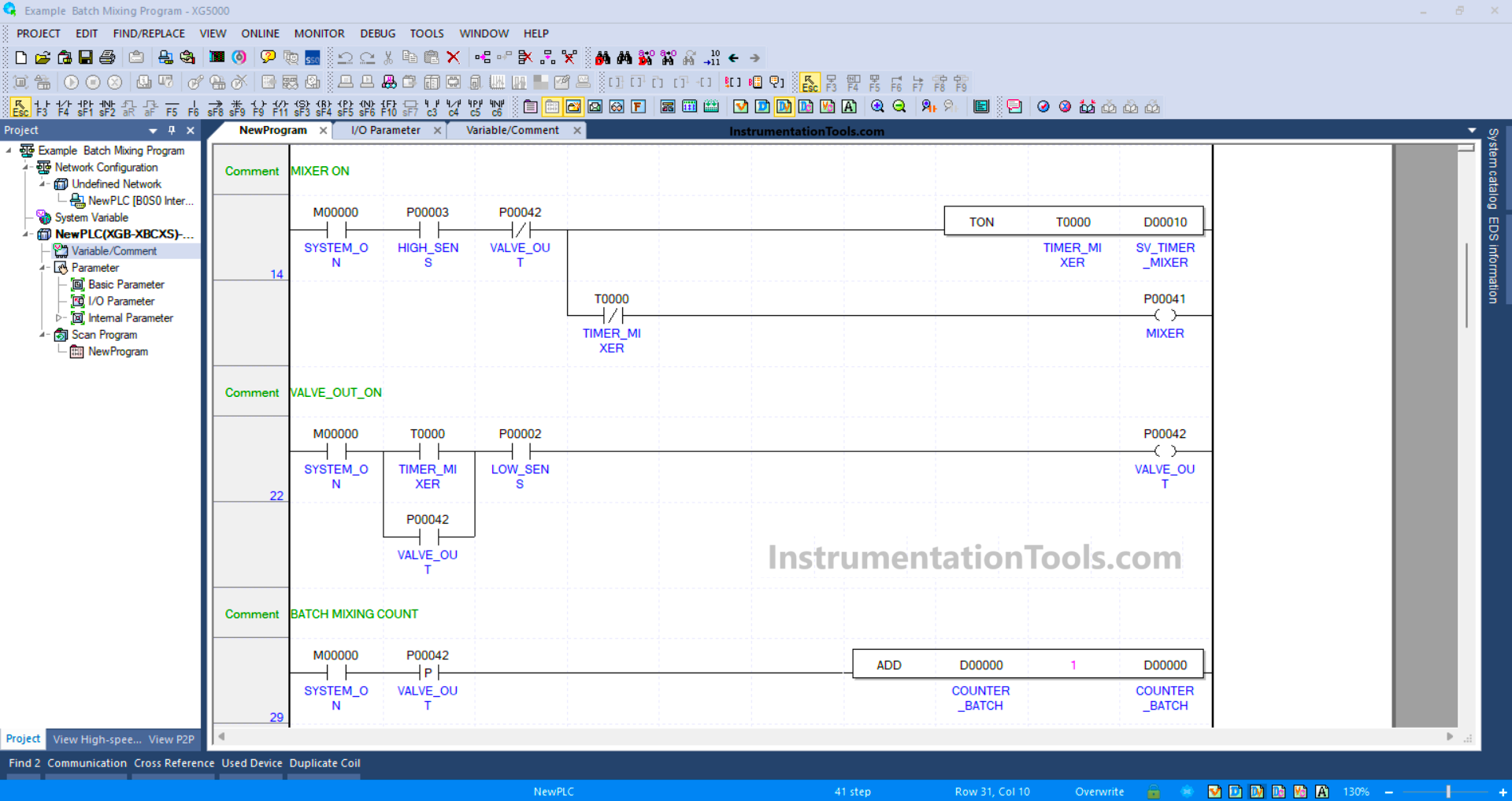
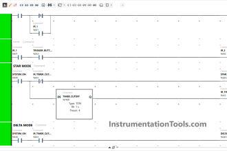
RUNG 14
In this Rung, when the NO contact of memory bit SYSTEM_ON (M00000) and the HIGH_SENS (P00003) Sensor in the HIGH state, the MIXER (P00041) Output will be ON and the TIMER_MIXER (T0000) Timer will start counting.
When the TIMER_MIXER (T0000) Timer has finished counting, the MIXER Output (P00041) will be OFF.
RUNG 22
When the NO contact of memory bit SYSTEM_ON (M00000), Timer TIMER_MIXER (T0000), and LOW_SENS (P00002) Sensor in the HIGH state, the VALVE_OUT (P00042) Output will be OPEN.
The VALVE_OUT (P00042) Output will remain in the OPEN state even though the NO contact of TIMER_MIXER (T0000) Timer is in the LOW state because it uses the Latching Function.
The VALVE_OUT (P00042) Output will become CLOSE if there is NO contact with the LOW_SENS (P00002) Sensor or memory bit SYSTEM_ON (M00000), which becomes a LOW state.
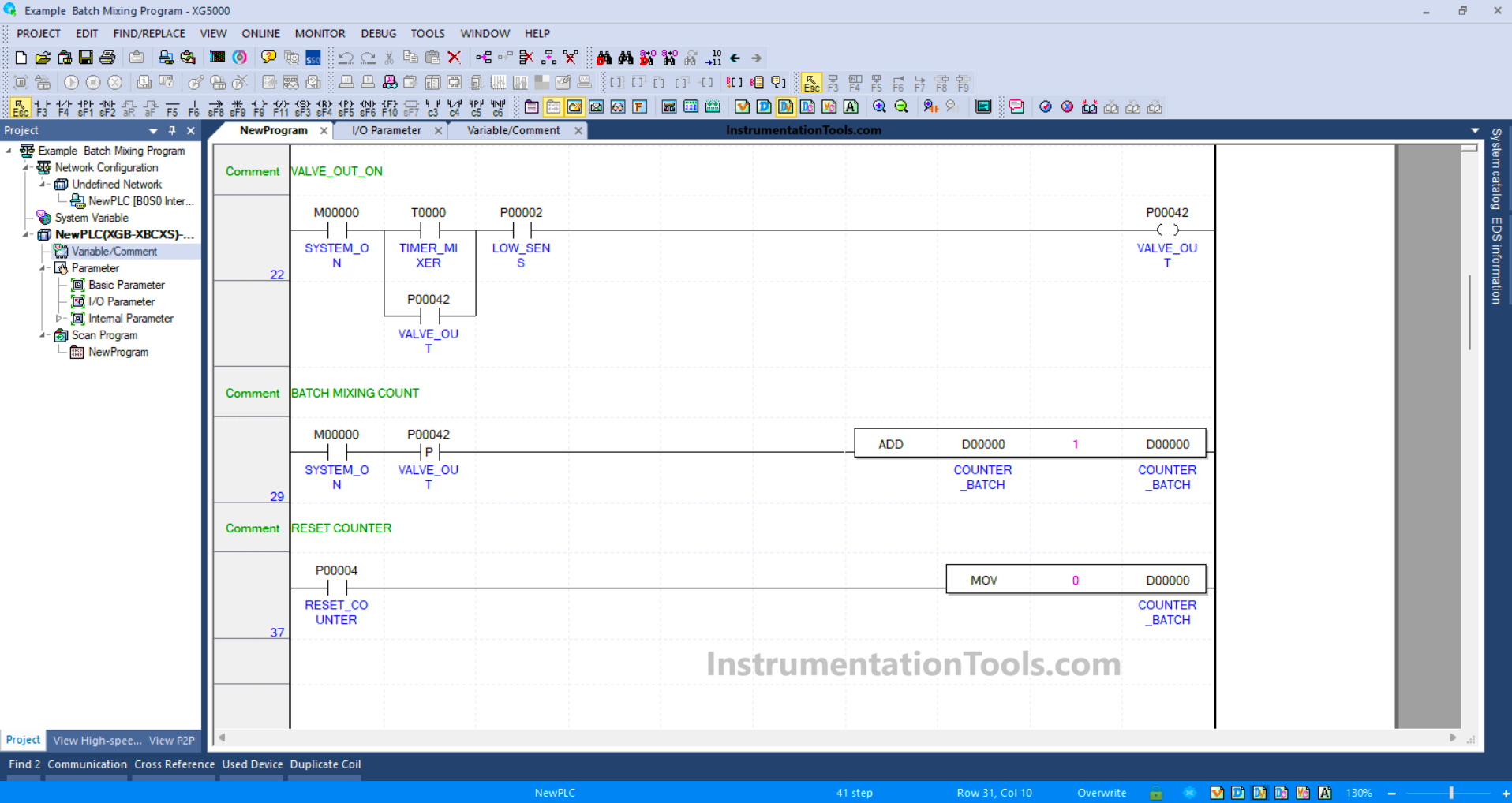
RUNG 29
The memory word COUNTER_BATCH (D00000) will increase by (+1) when the NO contacts of VALVE_OUT (P00042) and memory bit SYSTEM_ON (M00000) are in the HIGH state.
The ADD instruction will add a value (+1) to the memory word COUNTER_BATCH (D00000) each time it is activated.
RUNG 37
In this Rung, the MOV Instruction will move the zero value “0” to word memory COUNTER_BATCH (D00000) when the RESET_COUNTER (P00004) button is Pressed.
Read Next:
- PLC Logic Train Detection and Gate Operation
- Weighing with Labeling PLC Automation Logic
- Functional Block Diagram Analog Alarm Logic
- Timer-Based Sequential PLC Programming
- PLC Programming for Baking with Auto Mode