Inst ToolsInst ToolsInst Tools
  • Courses
  • Videos
  • Q & A
    • Interview
      • Instrumentation
      • Electronics
      • Electrical
      • Practical Questions
    • MCQ
      • Instrumentation MCQ
      • Electrical MCQ
      • Electronics MCQ
      • Control Systems MCQ
      • Analog Electronics MCQ
      • Digital Electronics MCQ
      • Power Electronics MCQ
      • Microprocessor MCQ
      • Multiple Choice Questions
  • EE
    • Electronics
      • Electronics Q & A
      • Electronic Basics
      • Electronic Devices & Circuits
      • Electronics Animation
      • Digital Electronics
    • Electrical
      • Electrical Basics
      • Electrical Q & A
      • Power Electronics
      • Electrical Machines
      • Electrical Animation
      • Power Systems
      • Switchgear & Protection
      • Transmission & Distribution
  • Measure
    • Control Valves
    • Calibration
    • Temperature
    • Pressure
    • Flow
    • Level
    • Analyzers
    • Switches
    • Vibration
    • Solenoid Valve
  • Control
    • PLC Tutorials
    • Control Systems
    • Safety Instrumented System (SIS)
    • Communication
    • Fire & Gas System
  • More
    • Design
    • Tools
    • Animation
    • Basics
    • Formulas
    • Standards
    • TextBooks
    • Common
    • Software
    • Excel Tools
    • Erection & Commissioning
    • Process Fundamentals
    • Videos
    • Books
Search
All rights reserved. Reproduction in whole or in part without written permission is prohibited.
Reading: Developing PLC Logic for Water Pumping and Chemical Addition
Share
Notification Show More
Font ResizerAa
Inst ToolsInst Tools
Font ResizerAa
  • Courses
  • PLC Tutorials
  • Control Systems
Search
  • Courses
  • Videos
  • Q & A
    • Interview
    • MCQ
  • EE
    • Electronics
    • Electrical
  • Measure
    • Control Valves
    • Calibration
    • Temperature
    • Pressure
    • Flow
    • Level
    • Analyzers
    • Switches
    • Vibration
    • Solenoid Valve
  • Control
    • PLC Tutorials
    • Control Systems
    • Safety Instrumented System (SIS)
    • Communication
    • Fire & Gas System
  • More
    • Design
    • Tools
    • Animation
    • Basics
    • Formulas
    • Standards
    • TextBooks
    • Common
    • Software
    • Excel Tools
    • Erection & Commissioning
    • Process Fundamentals
    • Videos
    • Books
Follow US
All rights reserved. Reproduction in whole or in part without written permission is prohibited.
Inst Tools > Blog > PLC Tutorials > Developing PLC Logic for Water Pumping and Chemical Addition

Developing PLC Logic for Water Pumping and Chemical Addition

Developing PLC logic for water pumping, filtration for 30 seconds, chemical addition for 5 seconds, and then transfer the water.

Last updated: May 4, 2024 12:12 pm
Editorial Staff
PLC Tutorials
No Comments
Share
5 Min Read
SHARE

Developing PLC logic for water pumping, filtration for 30 seconds, chemical addition for 5 seconds, and then transfer the water.

Contents
PLC Logic for Water PumpingPLC Training SeriesInputs and OutputsLadder DiagramProgram DescriptionPLC Program Result

We encourage students to utilize this PLC programming example for educational purposes and it provides an opportunity to learn the ladder logic through simple applications.

PLC Logic for Water Pumping

Problem Statement:

Design a PLC ladder logic for the following application.

We are using one toggle switch to control Pump 1, Filtration, Chemical, and Pump 2.

Start the Water Pump 1 to transfer the water. Then Filtration for 30 seconds, then the addition of Chemicals for 5 seconds, and then Pump 2 will be ON to transfer water into the storage tank.

PLC Training Series

This free PLC training series is designed for everyone to learn about PLC programming.

Watch this video to understand about this program.

Inputs and Outputs

Digital Inputs:

Start Button: I0.0

Digital Outputs:

Pump 1: Q0.0

Filtration: Q0.1

Chemical: Q0.2

Pump 2: Q0.3

Ladder Diagram
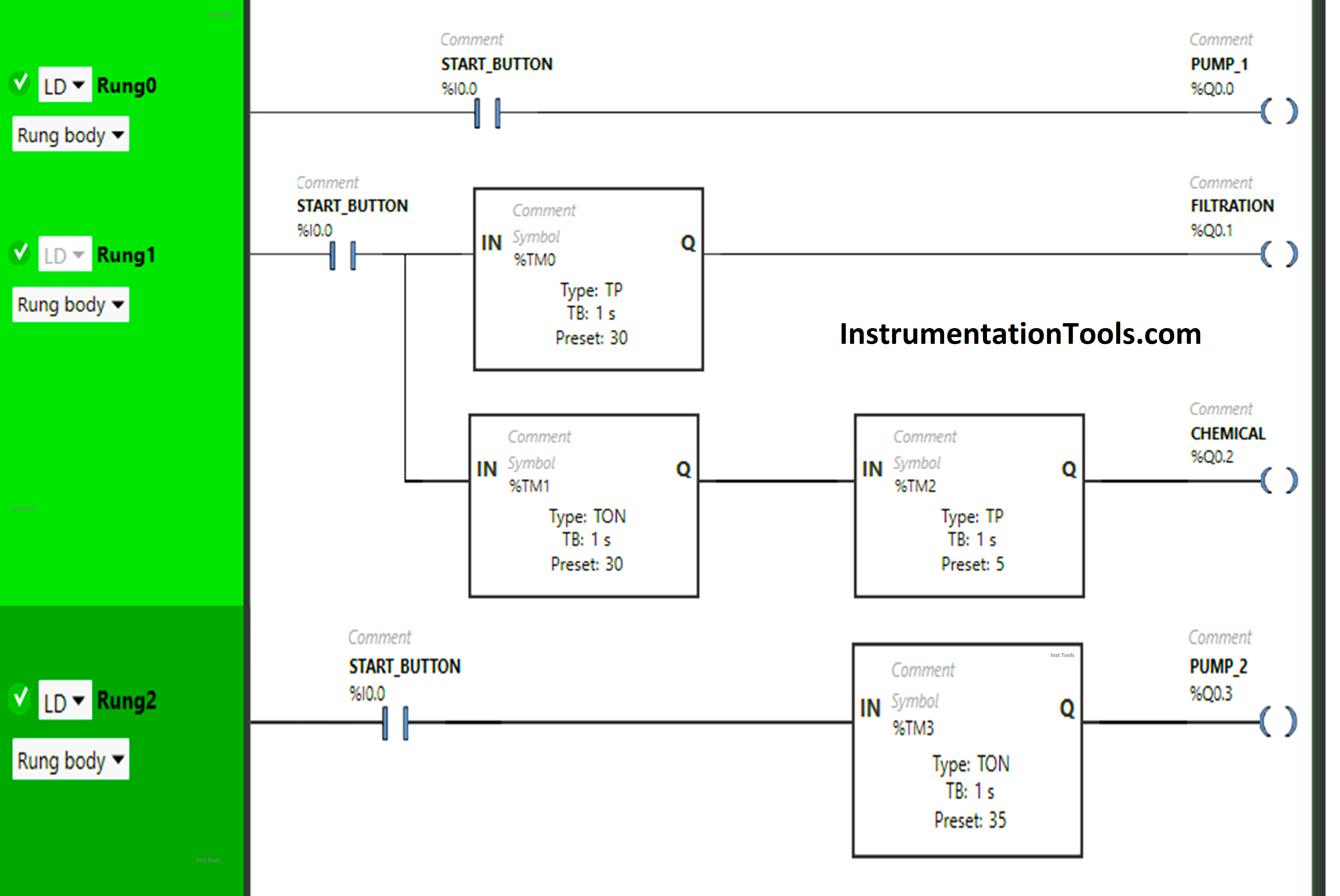
PLC Logic for Water Pumping and Chemical Addition

Program Description

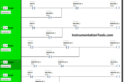
We have used Normally Open Contact for the Start Button (I0.0).

In Rung 0:

  1. Normally Open Contact is used for the Start Button (I0.0) to Turn ON the output Pump 1 (Q0.0).

In Rung 1:

  1. Normally Open Contact is used for the Start Button (I0.0) to Turn ON the outputs Filtration (Q0.1) and Chemical (Q0.2). 
  2. Timer type TP is used to Turn ON the output Filtration (Q0.1) for a limited time.
  3. Timer type TON is used to delay the turning ON time of the output Chemical (Q0.2) for some time.
  4. Timer type TP is used to Turn ON the output Chemical (Q0.2) for a limited time. 

In Rung 2:

  1. Normally Open Contact is used for the Start Button (I0.0) to Turn ON the outputs Pump 2 (Q0.3)
  2. Timer type TON is used to delay the turning ON time of the output Pump 2 (Q0.3) for some time.

PLC Program Result

Now we will see the PLC program result and observe the outputs.

Rung 0:

A water pumping control system with a PLC

When the Start Button (I0.0) turns ON, the output Pump 1 (Q0.0) will turn ON as Normally Open Contact used for the Start Button will pass the signal to output Pump 1 (Q0.0).

Rung 1:

When the Start Button (I0.0) is turned ON, the output Filtration (Q0.1) will turn ON for 30 seconds as Timer Function Block type TP is used to Turn ON the output Filtration (Q0.1) for a limited time. The time is set to 30 seconds.
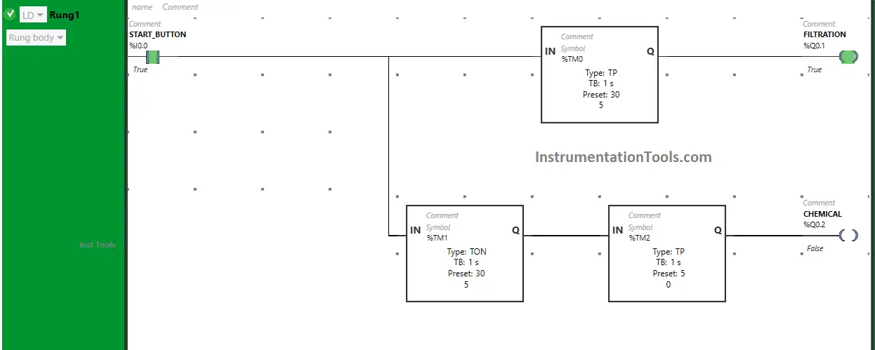
PLC Programming of a Water Pumping System

After 30 seconds, the output Filtration (Q0.1) will turn OFF. Also, when the Start Button (I0.0) is turned ON, the output chemical will turn ON after 30 seconds, (i.e immediately when the output Filtration (Q0.1) turns OFF) as Timer Function Block TON is used to delay the turning ON time of the output Chemical (Q0.2). The time is set to 30 seconds.
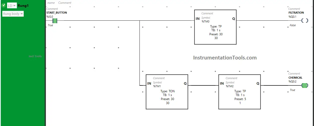
PLC Programming Example of Water Treatment Plant

After 30 seconds, the output Chemical (Q0.2) will turn ON but only for 5 seconds as Timer Function Block type TP is used to Turn ON the output Chemical (Q0.2) for a limited time. The time is set to 5 seconds. After 5 seconds, the output Chemical (Q0.2) will turn OFF.
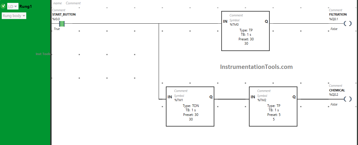
PLC Water Pump Control Program

Rung 2:

When the Start Button (I0.0) is turned ON, the output Pump 2 (Q0.3) will turn ON after 35 seconds (i.e. immediately when the output Chemical (Q0.2) turns OFF).

plc based on RO Plant

As Timer Function Block TON is used to delay the turning ON time of the output Pump 2 (Q0.3). The time is set to 35 seconds. After 35 seconds, the output Pump (Q0.3) will turn ON.

If you liked this article, please subscribe to our YouTube Channel for PLC and SCADA video tutorials.

You can also follow us on Facebook and Twitter to receive daily updates.

Read Next:

  • PLC Logic for Stairway Lighting
  • PLC Programming for Barrier Control
  • Traffic Lights PLC Logic using Timers
  • Control Spray Nozzle, Fans, Puncher
  • PLC Conveyor Forward and Reverse
Don't Miss Our Updates
Be the first to get exclusive content straight to your email.
We promise not to spam you. You can unsubscribe at any time.
Invalid email address
You've successfully subscribed !

Recommended Articles

Free PLC Training Software Download
Free SCADA Training Course
PLC Timer Practice Exercise: Coffee Machine Programming
Difference Between Industrial Computer (IPC) and Normal Computer (PC)
PLC to Start or Stop 3 Machines using 1 Switch Program
PLC Sinking and Sourcing Explanation
Share This Article
Facebook Whatsapp Whatsapp LinkedIn Copy Link
Share
Leave a Comment

Leave a Reply Cancel reply

Your email address will not be published. Required fields are marked *

Stay Connected

128.3kFollowersLike
69.1kFollowersFollow
208kSubscribersSubscribe
38kFollowersFollow

Categories

Recent Comments

  • William Snyder on Top Non-PLC Certification Courses for Automation Professionals
  • Kamli on Top Free PLC Software
  • Guifty Shimica on Top Non-PLC Certification Courses for Automation Professionals
  • Guifty Shimica on Top Non-PLC Certification Courses for Automation Professionals

Related Articles

PLC Project Examples for EcoStruxure Machine Expert

PLC Project Examples for EcoStruxure Machine Expert

Automatic Liquid Mixing Application

PLC Program for Automatic Liquid Mixing Application

Use of Regions in SCL Language

Use of Regions in SCL Language

Two Hand Control Logic

Two Hand Control Logic using PLC

TON Timer in RSlogix

Why is RTO used in the Place of TON Timer?

Automating Car Parking with Advanced PLC Logic

Complex Car Parking Logic in XG5000 LS Electric PLC

Speed Control of Pneumatic Cylinder (Explanation with PLC)

Speed Control of Pneumatic Cylinder (Explanation with PLC)

Online time of the PLC

System and Local Time in PLC

More Articles

Optimal Control Systems

The Infinite Time Regulator Problem

Electric Circuits Objective Questions

Electric Circuits Objective Questions – Set 5

Cavitation Test Setup

Cavitation Test Setup

DCS Program to Maintain Draft in Furnace

DCS Program to Maintain Draft in Furnace

Engineering Materials Objective Questions

Engineering Materials Objective Questions

Flow meter Turndown Ratio

Why Turndown Ratio is important when Selecting a Flow Meter?

orifice plate vent hole

What is the Purpose of Orifice Plate Drain Hole and Vent Hole?

Agriculture Projects

170+ Agriculture Engineering Projects List​

Follow US
All rights reserved. Reproduction in whole or in part without written permission is prohibited.
Welcome Back!

Sign in to your account

Username or Email Address
Password

Lost your password?