This is PLC Ladder Logic for Sensor Scaling with Offset. Make PLC program for the analog input scaling for several scales used in general applications.
PLC Ladder Logic for Sensor Scaling with Offset
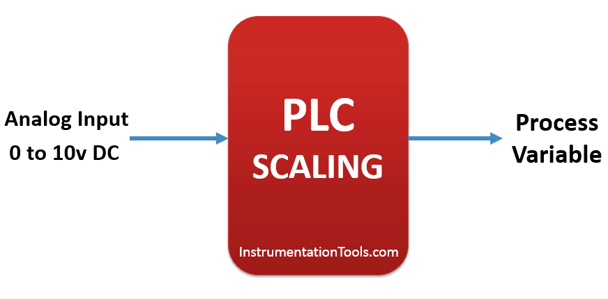
Solution
Here we consider different analog scale for explanation. Consider 0-10V DC analog input signal for this examples. We will use different scaling equation for the analog inputs like Temperature and Pressure Sensors.
Analog value is in current or voltage form so we need to convert this value into actual value. Here 0-10 V DC value is converted to actual value with instructions.
List of Inputs/Outputs
List of Inputs
- IW 64:-Analog input channel
M memory
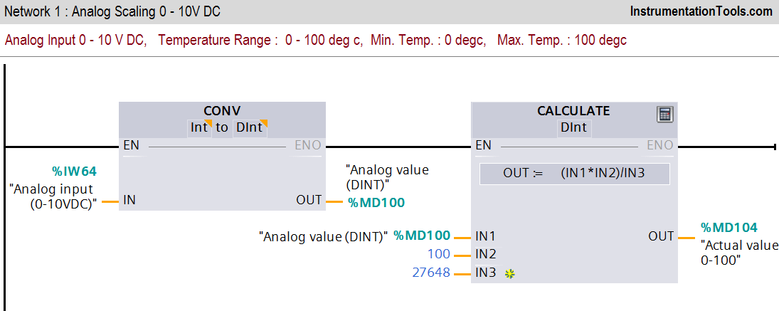
- MD100 :-Analog value
- MD104 :-Actual value (0-100 degree).
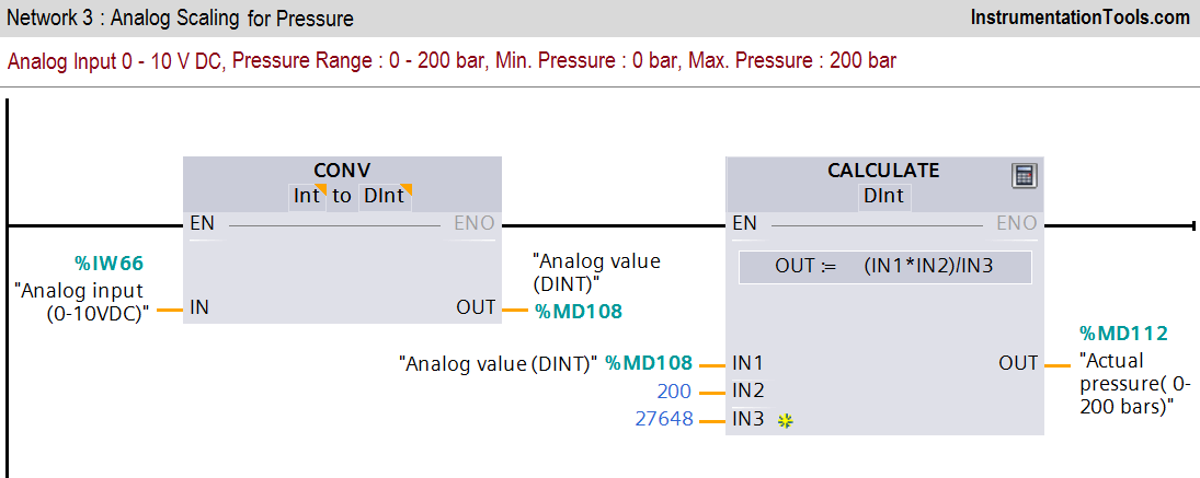
- MD108 :-Analog value
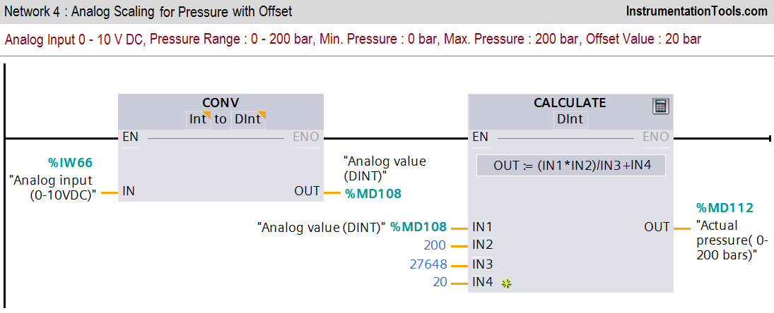
- MD112 :-Actual pressure (0-200 bars).
Ladder Diagram for Pressure and Temperature Sensors
Ladder Logic Description
Network 1 :-
In first network we have converted analog value into actual temperature. Actual analog value is in INT form so we need to convert in DINT for calculation purpose.
Here maximum temperature is 100 degree and minimum temperature is 0 degree.
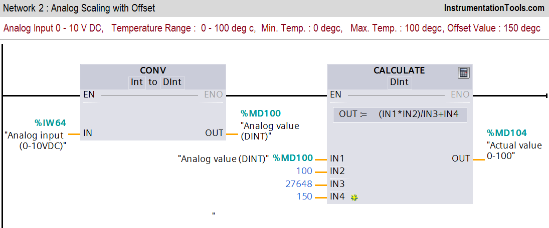
Network 2 :-
In this network offset value (150 degree) is added into scaling.
Network 3 :-
In this network we have taken pressure sensor scaling for the application. Pressure is scaled in the range between (0-200 bars).
Network 4 :-
In this network offset value (20 bar) is added into scaling as offset value.
Note:-
Above application may be different from actual application. This example is only for explanation purpose only. We can implement this logic in other PLC also. This is the simple application for several scales of analog value using PLC, we can use this concept in other examples also.
All parameters and graphical representations considered in this example are for explanation purpose only, parameters or representation may be different in actual applications. Also all interlocks are not considered in the application.
If you liked this article, then please subscribe to our YouTube Channel for PLC and SCADA video tutorials.
You can also follow us on Facebook and Twitter to receive daily updates.
Read Next:
