The most elementary objects in Ladder Diagram programming are contacts and coils, intended to mimic the contacts and coils of electromechanical relays.
Contacts and coils are discrete programming elements, dealing with Boolean (1 and 0; on and off; true and false) variable states.
Each contact in a Ladder Diagram PLC program represents the reading of a single bit in memory, while each coil represents the writing of a single bit in memory.
Discrete input signals to the PLC from real-world switches are read by a Ladder Diagram program by contacts referenced to those input channels.
In legacy PLC systems, each discrete input channel has a specific address which must be applied to the contact(s) within that program.
In modern PLC systems, each discrete input channel has a tag name created by the programmer which is applied to the contact(s) within the program.
Similarly, discrete output channels – referenced by coil symbols in the Ladder Diagram – must also bear some form of address or tag name label.
Also Read : Mis-conceptions of PLC Ladder Logic
To illustrate, we will imagine the construction and programming of a redundant flame-sensing system to monitor the status of a burner flame using three sensors.
The purpose of this system will be to indicate a “lit” burner if at least two out of the three sensors indicate flame.
If only one sensor indicates flame (or if no sensors indicate flame), the system will declare the burner to be un-lit.
The burner’s status will be visibly indicated by a lamp that human operators can readily see inside the control room area.
Our system’s wiring is shown in the following diagram:
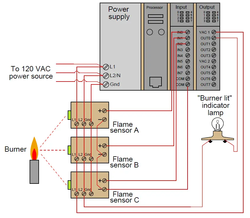
Each flame sensor outputs a DC voltage signal indicating the detection of flame at the burner, either on (24 volts DC) or off (0 volts DC).
These three discrete DC voltage signals are sensed by the first three channels of the PLC’s discrete input card.
The indicator lamp is a 120 volt light bulb, and so must be powered by an AC discrete output card, shown here in the PLC’s last slot.
To make the ladder program more readable, we will assign tag names (symbolic addresses) to each input and output bit in the PLC, describing its real-world device in an easily-interpreted format.
We will tag the first three discrete input channels as IN sensor A, IN sensor B, and IN sensor C, and the output as OUT burner lit.
A ladder program to determine if at least two out of the three sensors detect flame is shown here, with the tag names referencing each contact and coil:
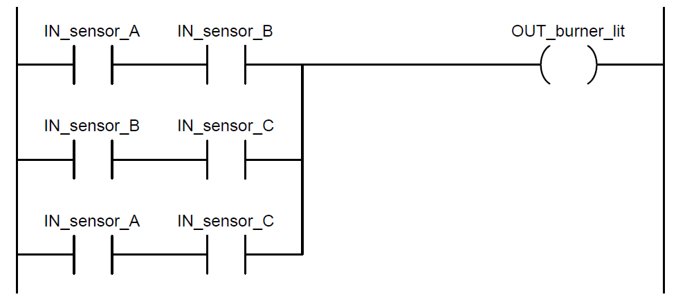
Series-connected contacts in a Ladder Diagram perform the logical AND function, while parallel contacts perform the logical OR function. Thus, this two-out-of-three flame-sensing program could be verbally described as:
“Burner is lit if either A and B, or either B and C, or either A and C”
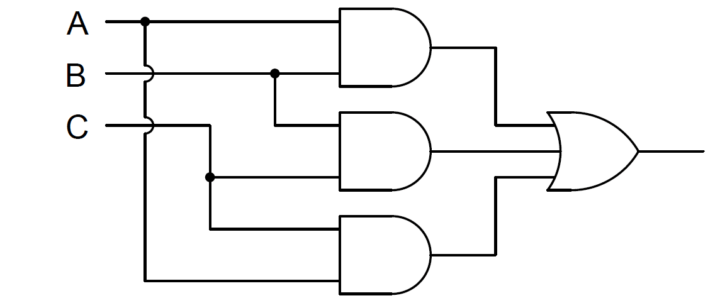
An alternate way to express this is to use the notation of Boolean algebra, where multiplication represents the AND function and addition represents the OR function:
Burner_lit = AB + BC + AC
Yet another way to represent this logical relationship is to use logic gate symbols:
To illustrate how this program would work, we will consider a case where flame sensors B and C detect flame, but sensor A does not (Note1).
This represents a two-out-of-three-good condition, and so we would expect the PLC to turn on the “Burner lit” indicator light as programmed.
From the perspective of the PLC’s rack, we would see the indicator LEDs for sensors B and C lit up on the discrete input card, as well as the indicator LED for the lamp’s output channel:
Note 1 : The most likely reason why one out of two flame sensors might not detect the presence of a flame is some form of misalignment or fouling of the flame sensor.
In fact, this is a good reason for using a 2-out-of-3 flame detection system rather than a simplex (1-out-of-1) detector scheme: to make the system more tolerant of occasional sensor problems without compromising burner safety.
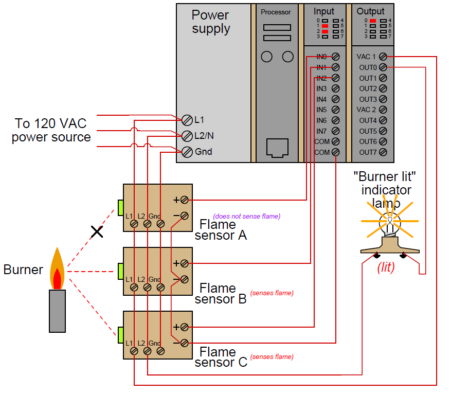
Those two energized input channels “set” bits (1 status) in the PLC’s memory representing the status of flame sensors B and C. Flame sensor A’s bit will be “clear” (0 status) because its corresponding input channel is de-energized.
The fact that the output channel LED is energized (and the “Burner lit” indicator lamp is energized) tells us the PLC program has “set” that corresponding bit in the PLC’s output memory register to a “1” state.
A display of input and output register bits shows the “set” and “reset” states for the PLC at this moment in time:

Examining the Ladder Diagram program with status indication enabled, we see how only the middle contact pair is passing “virtual power” to the output coil:
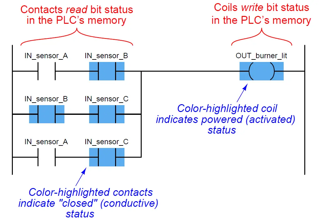
Recall that the purpose of a contact in a PLC program is to read the status of a bit in the PLC’s memory.
These six “virtual contacts” read the three input bits corresponding to the three flame sensors.
Each normally-open “contact” will “close” when its corresponding bit has a value of 1, and will “open” (go to its normal state) when its corresponding bit has a value of 0.
Thus, we see here that the two contacts corresponding to sensor A appear without highlighting (representing no “conductivity” in the virtual relay circuit) because the bit for that input is reset (0).
The two contacts corresponding to sensor B and the two contacts corresponding to sensor C all appear highlighted (representing “conductivity” in the virtual circuit) because their bits are both set (1).
Recall also that the purpose of a coil in a PLC program is to write the status of a bit in the PLC’s memory.
Here, the “energized” coil sets the bit for the PLC output 0 to a “1” state, thus activating the real-world output and sending electrical power to the “Burner lit” lamp.
Note that the color highlighting does not indicate a virtual contact is conducting virtual power, but merely that it is able to conduct power. Color highlighting around a virtual coil, however, does indicate the presence of virtual “power” at that coil.
Contacts and relays are not just useful for implementing simple logic functions, but they may also perform latching functions as well.
A very common application of this in industrial PLC systems is a latching start/stop program for controlling electric motors by means of momentary-contact push-button switches.
As before, this functionality will be illustrated by means of an hypothetical example circuit and program:
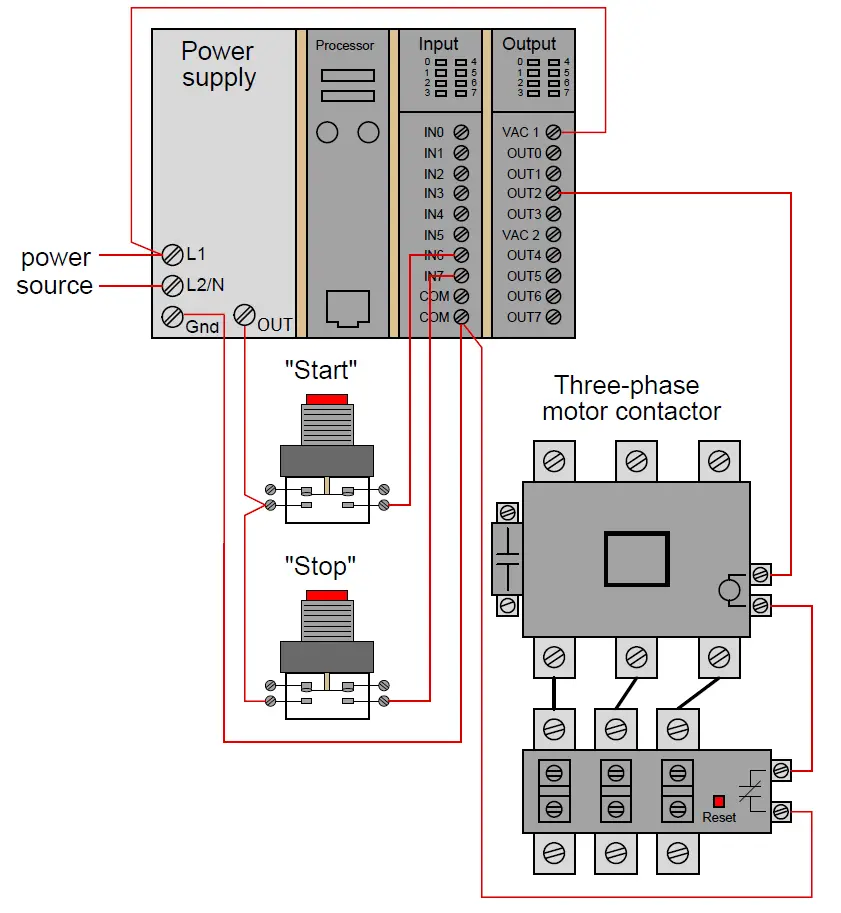
In this system, two push-button switches are connected to discrete inputs on a PLC, and the PLC in turn energizes the coil of a motor contactor relay by means of one of its discrete outputs.
An overload contact is wired directly in series with the contactor coil to provide motor over-current protection, even in the event of a PLC failure where the discrete output channel remains energized ( note 2 ). The ladder program for this motor control system would look like this:
Note 2 : While it is possible to wire the overload contact to one of the PLC’s discrete input channels and then program a virtual overload contact in series with the output coil to stop the motor in the event of a thermal overload, this strategy would rely on the PLC to perform a safety function which is probably better performed by hard-wired circuitry.

Pressing the “Start” pushbutton energizes discrete input channel 6 on the PLC, which “closes” the virtual contact in the PLC program labeled IN switch Start.
The normally-closed virtual contact for input channel 7 (the “Stop” pushbutton) is already closed by default when the “Stop” button is not being pressed, and so the virtual coil will receive “power” when the “Start” pushbutton is pressed and the “Stop” pushbutton is not.
Also Read : History of PLC
Note the seal-in contact bearing the exact same label as the coil: OUT contactor. At first it may seem strange to have both a contact and a coil in a PLC program labeled identically (Note 3 ), since contacts are most commonly associated with inputs and coils with outputs, but this makes perfect sense if you realize the true meaning of contacts and coils in a PLC program: as read and write operations on bits in the PLC’s memory.
The coil labeled OUT contactor writes the status of that bit, while the contact labeled OUT contactor reads the status of that same bit. The purpose of this contact, of course, is to latch the motor in the “on” state after a human operator has released his or her finger from the “Start” pushbutton.
Note 3 : A very common misconception among students first learning PLC Ladder Diagram programming is to always associate contacts with PLC inputs and coils with PLC outputs, thus it seems weird to have a contact bear the same label as an output. However, this is a false association. In reality, contacts and coils are read and write instructions, and thus it is possible to have the PLC read one of its own output bits as a part of some logic function. What would be truly strange is to label a coil with an input bit address or tag name, since the PLC is not electrically capable of setting the real-world energization status of any input channels.
This programming technique is known as feedback, where an output variable of a function (in this case, the feedback variable is OUT contactor) is also an input to that same function.
The path of feedback is implicit rather than explicit in Ladder Diagram programming, with the only indication of feedback being the common name shared by coil and contact.
Other graphical programming languages (such as Function Block) have the ability to show feedback paths as connecting lines between function outputs and inputs, but this capacity does not exist in Ladder Diagram.
A step-by-step sequence showing the operation and status of this simple program illustrates how the seal-in contact functions, through a start-up and shut-down cycle of the motor:
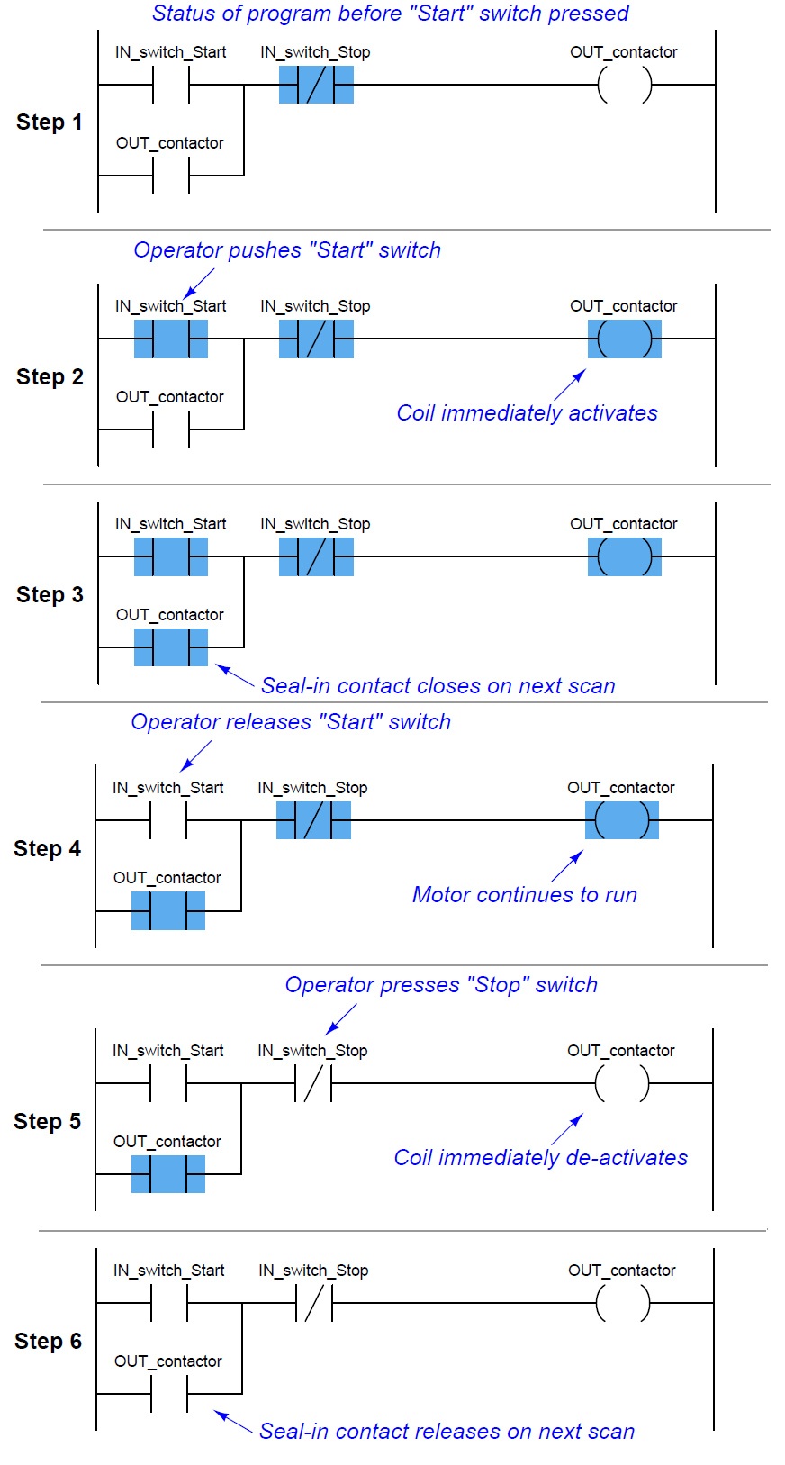
This sequence helps illustrate the order of evaluation or scan order of a Ladder Diagram program. The PLC reads a Ladder Diagram from left to right, top to bottom, in the same general order as a human being reads sentences and paragraphs written in English.
However, according to the IEC 61131-3 standard, a PLC program must evaluate (read) all inputs (contacts) to a function before determining the status of a function’s output (coil or coils).
In other words, the PLC does not make any decision on how to set the state of a coil until all contacts providing power to that coil have been read.
Once a coil’s status has been written to memory, any contacts bearing the same tag name will update with that status on subsequent rungs in the program.
Step 5 in the previous sequence is particularly illustrative. When the human operator presses the “Stop” pushbutton, the input channel for IN switch Stop becomes activated, which “opens” the normally-closed virtual contact IN switch Stop.
Upon the next scan of this program rung, the PLC evaluates all input contacts (IN switch Start, IN switch Stop, and OUT contactor) to check their status before deciding what status to write to the OUT contactor coil.
Seeing that the IN switch Stop contact has been forced open by the activation of its respective discrete input channel, the PLC writes a “0” (or “False”) state to the OUT contactor coil.
However, the OUT contactor feedback contact does not update until the next scan, which is why you still see it color-highlighted during step 5.
Also Read : PLC Digital I/O Modules
A potential problem with this system as it is designed is that the human operator loses control of the motor in the event of an “open” wiring failure in either pushbutton switch circuit.
For instance, if a wire fell off a screw contact for the “Start” pushbutton switch circuit, the motor could not be started if it was already stopped.
Similarly, if a wire fell off a screw contact for the “Stop” pushbutton switch circuit, the motor could not be stopped if it was already running.
In either case, a broken wire connection acts the same as the pushbutton switch’s “normal” status, which is to keep the motor in its present state.
Some applications, this failure mode would not be a severe problem. Many applications, though, it is quite dangerous to have a running motor that cannot be stopped.
For this reason, it is customary to design motor start/stop systems a bit differently from what has been shown here.
In order to build a “fail-stop” motor control system with our PLC, we must first re-wire the pushbutton switch to use its normally-closed (NC) contact:
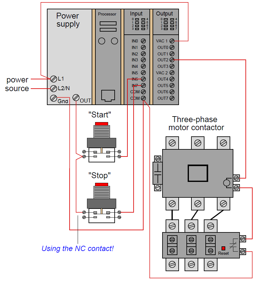
This keeps discrete input channel 7 activated when the pushbutton is unpressed. When the operator presses the “Stop” pushbutton, the switch’s contact will be forced open, and input channel 7 will de-energize.
If a wire happens to fall off a screw terminal in the “Stop” switch circuit, input channel 7 will de-energize just the same as if someone pressed the “Stop” pushbutton, which will automatically shut off the motor.
In order for the PLC program to work properly with this new switch wiring, the virtual contact for IN switch Stop must be changed from a normally-closed (NC) to a normally-open (NO):
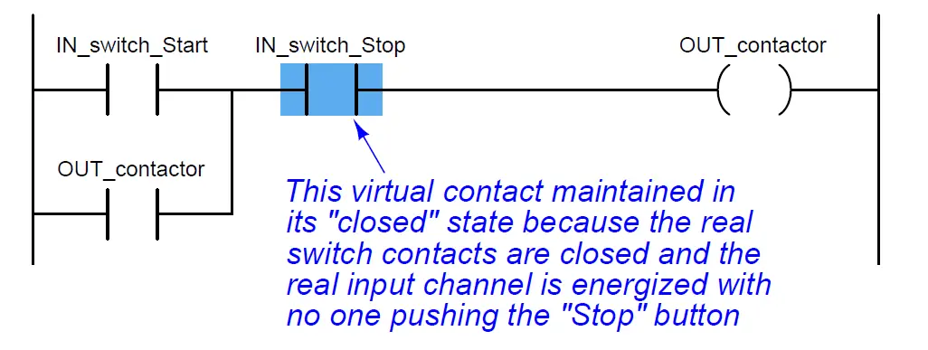
As before, the IN switch Stop virtual contact is in the “closed” state when no one presses the “Stop” switch, enabling the motor to start any time the “Start” switch is pressed.
Similarly, the IN switch Stop virtual contact will open any time someone presses the “Stop” switch, thus stopping virtual “power” from flowing to the OUT contactor coil.
Although this is a very common way to build PLC-controlled motor start/stop systems – with an NC pushbutton switch and an NO “Stop” virtual contact – students new to PLC programming often find this logical reversal confusing.
Perhaps the most common reason for this confusion is a mis-understanding of the “normal” concept for switch contacts, be they real or virtual. The IN switch Stop virtual contact is programmed to be normally-open (NO), but yet it is typically found in the closed state.
Recall that the “normal” status of any switch is its status while in a resting condition of no stimulation, not necessarily its status while the process is in a “normal” operating mode.
The “normally-open” virtual contact IN switch Stop is typically found in the closed state because its corresponding input channel is typically found energized, owing to the normally-closed pushbutton switch contact, which passes real electrical power to the input channel while no one presses the switch.
Just because a switch is configured as normally-open does not necessarily mean it will be typically found in the open state! The status of any switch contact, whether real or virtual, is a function of its configuration (NO versus NC) and the stimulus applied to it.
Another concern surrounding real-world wiring problems is what this system will do if the motor contactor coil circuit opens for any reason.
An open circuit may develop as a result of a wire falling off a screw terminal, or it may occur because the thermal overload contact tripped open due to an over-temperature event. The problem with our motor start/stop system as designed is that it is not “aware” of the contactor’s real status.
In other words, the PLC “thinks” the contactor will be energized any time discrete output channel 2 is energized, but that may not actually be the case if there is an open fault in the contactor’s coil circuit.
Also Read : How PLC Controls a Motor ?
This may lead to a dangerous condition if the open fault in the contactor’s coil circuit is later cleared. Imagine an operator pressing the “Start” switch but noticing the motor does not actually start.
Wondering why this may be, he or she goes to look at the overload relay to see if it is tripped. If it is tripped, and the operator presses the “Reset” button on the overload assembly, the motor will immediately start because the PLC’s discrete output has remained energized all the time following the pressing of the “Start” switch.
Having the motor start up as soon as the thermal overload is reset may come as a surprise to operations personnel, and this could be quite dangerous if anyone happens to be near the motor-powered machinery when it starts.
What would be safer is a motor control system that refuses to “latch” on unless the contactor actually energizes when the “Start” switch is pressed. For this to be possible, the PLC must have some way of sensing the contactor’s status.
In order to make the PLC “aware” of the contactor’s real status, we may connect the auxiliary switch contact to one of the unused discrete input channels on the PLC, like this:
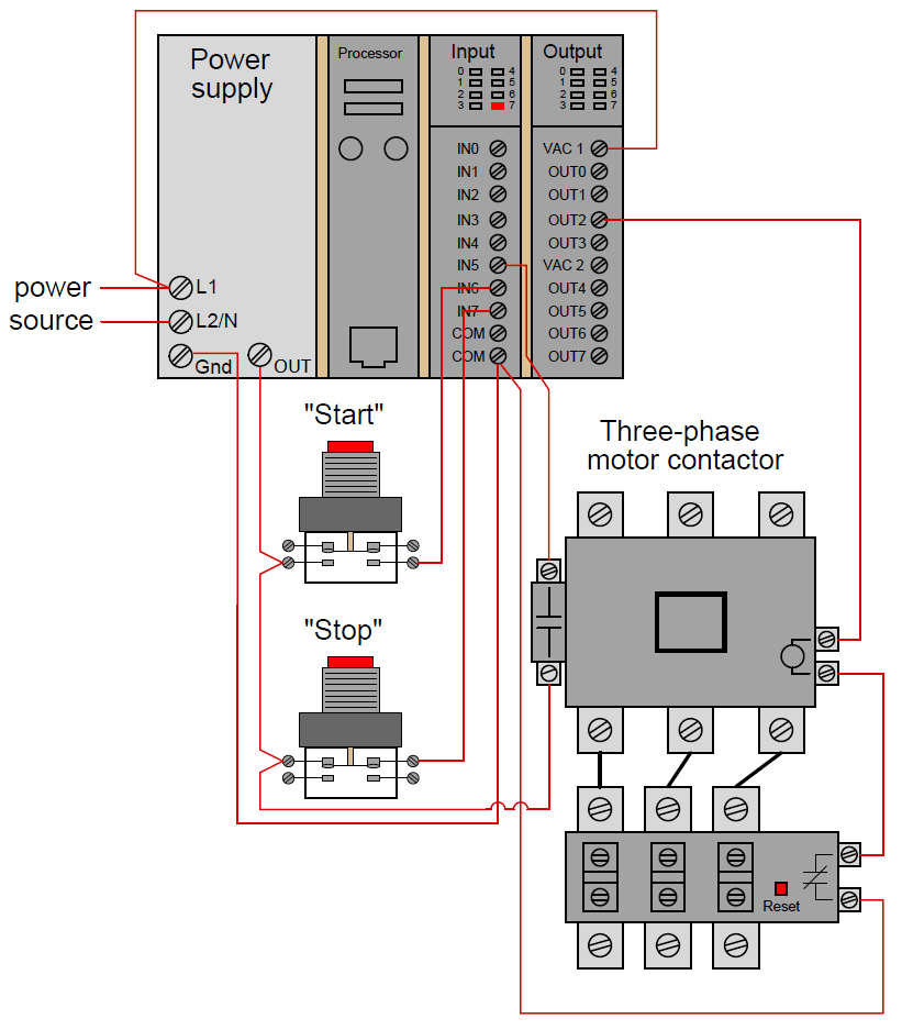
Now, the PLC is able to sense the real-time status of the contactor via input channel 5.
We may modify the PLC program to recognize this status by assigning a new tag name to this input (IN contactor aux) and using a normally-open virtual contact of this name as the seal-in contact instead of the OUT contactor bit:

Now, if the contactor fails to energize for any reason when the operator presses the “Start” switch, the PLC’s output will fail to latch when the “Start” switch is released.
When the open fault in the contactor’s coil circuit is cleared, the motor will not immediately start up, but rather wait until the operator presses the “Start” switch again, which is a much safer operating characteristic than before.
A special class of virtual “coil” used in PLC ladder programming that bears mentioning is the “latching” coil. These usually come in two forms: a set coil and a reset coil.
Unlike a regular “output” coil that positively writes to a bit in the PLC’s memory with every scan of the program, “set” and “reset” coils only write to a bit in memory when energized by virtual power. Otherwise, the bit is allowed to retain its last value.
A very simple motor start/stop program could be written with just two input contacts and two of these latching coils (both bearing the same tag name, writing to the same bit in memory):
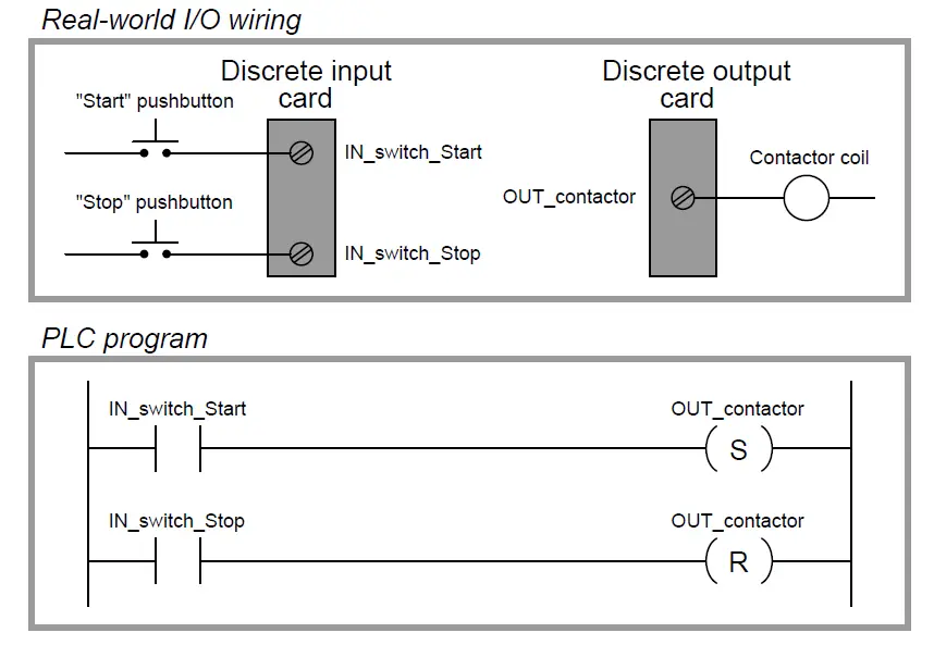
Note the use of a normally-open (NO) pushbutton switch contact (again!), with no auxiliary contact providing status indication of the contactor to the PLC. This is a very minimal program, shown for the strict purpose of illustrating the use of “set” and “reset” latching coils in Ladder Diagram PLC programming.
“Set” and “Reset” coils ( Referred to as “Latch” and “Unlatch” coils ) are examples of what is known in the world of PLC programming as retentive instructions. A “retentive” instruction retains its value after being virtually “de-energized” in the Ladder Diagram “circuit.”
A standard output coil is non-retentive, which means it does not “latch” when de-energized. The concept of retentive and non-retentive instructions will appear again as we explore PLC programming, especially in the area of timers.
Ordinarily, we try to avoid multiple coils bearing the same label in a PLC Ladder Diagram program. With each coil representing a “write” instruction, multiple coils bearing the same name represents multiple “write” operations to the same bit in the PLC’s memory.
Here, with latching coils, there is no conflict because each of the coils only writes to the OUT contactor bit when its respective contact is energized. So long as only one of the pushbutton switches is actuated at a time, there is no conflict between the identically-named coils.
This raises the question: what would happen if both pushbutton switches were simultaneously pressed? What would happen if both “Set” and “Reset” coils were “energized” at the same time? The result is that the OUT contactor bit would first be “set” (written to a value of 1) then “reset” (written to a value of 0) in that order as the two rungs of the program were scanned from top to bottom.
PLCs typically do not typically update their discrete I/O registers while scanning the Ladder Diagram program (this operation takes place either before or after each program scan), so the real discrete output channel status will be whatever the last write operation told it to be, in this case “reset” (0, or off).
Even if the discrete output is not “confused” due to the conflicting write operations of the “Set” and “Reset” coils, other rungs of the program written between the “Set” and “Reset” rungs might be.
Consider for example a case where there were other program rungs following the “Set” and “Reset” rungs reading the status of the OUT contactor bit for some purpose.
Those other rungs would indeed become “confused” because they would see the OUT contactor bit in the “set” state while the actual discrete output of the PLC (and any rungs following the “Reset” rung) would see the OUT contactor bit in the “reset” state:
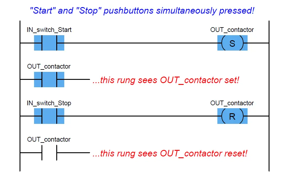
Multiple (non-retentive) output coils with the same memory address are almost always a programming faux pax for this reason, but even retentive coils which are designed to be used in matched pairs can cause trouble if the implications of simultaneous energization are not anticipated.
Multiple contacts with identical addresses are no problem whatsoever, because multiple “read” operations to the same bit in memory will never cause a conflict.
The IEC 61131-3 PLC programming standard specifies transition-sensing contacts as well as the more customary “static” contacts. A transition-sensing contact will “actuate” only for a duration of one program scan, even if its corresponding bit remains active.
Two types of transition-sensing Ladder Diagram contacts are defined in the IEC standard: one for positive transitions and another for negative transitions.
The following example shows a wiring diagram, Ladder Diagram program, and a timing diagram demonstrating how each type of transition-sensing contact functions when stimulated by a real (electrical) input signal to a discrete channel:
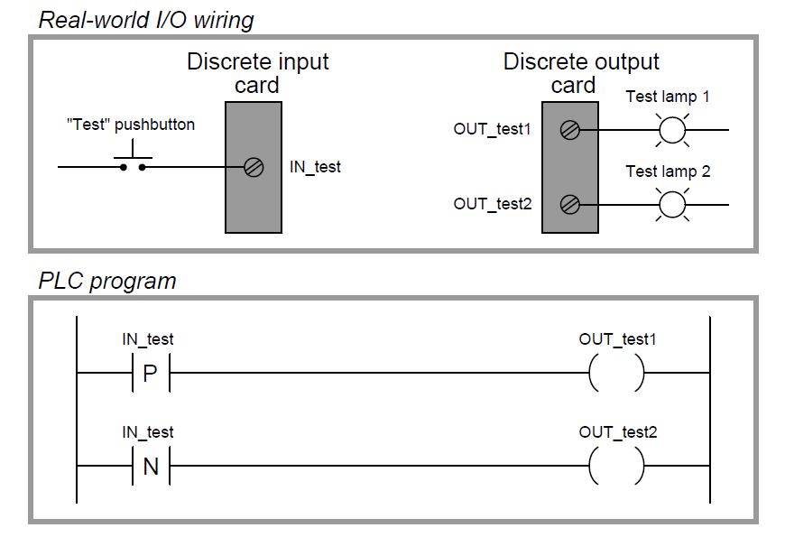
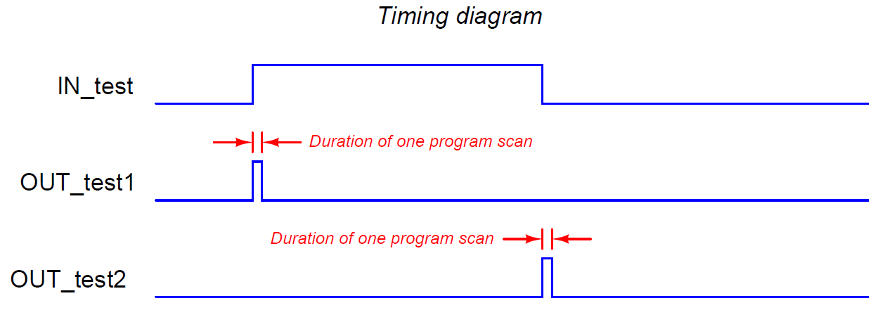
When the pushbutton switch is pressed and the discrete input energized, the first test lamp will blink “on” for exactly one scan of the PLC’s program, then return to its off state.
The positive transition contact (with the letter “P” inside) activates the coil OUT test1 only during the scan it sees the status of IN test transition from “false” to “true,” even though the input remains energized for many scans after that transition.
Conversely, when the pushbutton switch is released and the discrete input de-energizes, the second test lamp will blink “on” for exactly one scan of the PLC’s program then return to its off state.
The negative-transition contact (with the letter “N” inside) activates the coil OUT test2 only during the scan it sees the status of IN test transition from “true” to “false,” even though the input remains de-energized for many scans after that transition:
It should be noted that the duration of a single PLC program scan is typically very short: measured in milliseconds. If this program were actually tested in a real PLC, you would probably not be able to see either test lamp light up, since each pulse is so short-lived.
Transitional contacts are typically used any time it is desired to execute an instruction just one time following a “triggering” event, as opposed to executing that instruction over and over again so long as the event status is maintained “true.”
Contacts and coils represent only the most basic of instructions in the Ladder Diagram PLC programming language.
Also Read : How PLC Controls a ON/OFF Valve ?
Credits : by Tony R. Kuphaldt – Creative Commons Attribution 4.0 License
PLC Tutorials :
What is Programmable Logic Controller ?
What is Ladder Diagram Programming ?
History of Programmable Logic Controllers
Mis-conceptions of PLC Ladder Logic
Contacts and coils in PLC
Digital Input and Output Modules
Analog I/O and Network I/O
PLC Input/Output Modules
Memory Mapping in PLC
Analog Input Scaling
PLC Example with Switches
Counter Instructions
Timer Instructions
Math instructions
Data Instructions
Ladder Logic Questions
If you liked this article, then please subscribe to our YouTube Channel for PLC and SCADA video tutorials.
You can also follow us on Facebook and Twitter to receive daily updates.





Excellent instruction, Thanks
Excellent contribution, thanks for the both of you.