Inst ToolsInst ToolsInst Tools
  • Courses
  • Automation
    • PLC
    • Control System
    • Safety System
    • Communication
    • Fire & Gas System
  • Instrumentation
    • Design
    • Pressure
    • Temperature
    • Flow
    • Level
    • Vibration
    • Analyzer
    • Control Valve
    • Switch
    • Calibration
    • Erection & Commissioning
  • Interview
    • Instrumentation
    • Electrical
    • Electronics
    • Practical
  • Q&A
    • Instrumentation
    • Control System
    • Electrical
    • Electronics
    • Analog Electronics
    • Digital Electronics
    • Power Electronics
    • Microprocessor
  • Request
Search
  • Books
  • Software
  • Projects
  • Process
  • Tools
  • Basics
  • Formula
  • Power Plant
  • Root Cause Analysis
  • Electrical Basics
  • Animation
  • Standards
  • 4-20 mA Course
  • Siemens PLC Course
Reading: Basic PLC Exercise on Heater and Cooler for Students
Share
Font ResizerAa
Inst ToolsInst Tools
Font ResizerAa
  • Courses
  • Design
  • PLC
  • Interview
  • Control System
Search
  • Courses
  • Automation
    • PLC
    • Control System
    • Safety System
    • Communication
    • Fire & Gas System
  • Instrumentation
    • Design
    • Pressure
    • Temperature
    • Flow
    • Level
    • Vibration
    • Analyzer
    • Control Valve
    • Switch
    • Calibration
    • Erection & Commissioning
  • Interview
    • Instrumentation
    • Electrical
    • Electronics
    • Practical
  • Q&A
    • Instrumentation
    • Control System
    • Electrical
    • Electronics
    • Analog Electronics
    • Digital Electronics
    • Power Electronics
    • Microprocessor
  • Request
Follow US
All rights reserved. Reproduction in whole or in part without written permission is prohibited.
Inst Tools > Blog > PLC Tutorials > Basic PLC Exercise on Heater and Cooler for Students

Basic PLC Exercise on Heater and Cooler for Students

Basic PLC exercise on heater and cooler based on the low-level and high-level temperature sensors for students.

Last updated: May 6, 2024 10:35 am
Editorial Staff
PLC Tutorials
2 Comments
Share
4 Min Read
SHARE

Basic PLC exercise on heater and cooler based on the low-level and high-level temperature sensors for students.

Contents
Heater and Cooler PLC ExerciseLadder Logic VideosInputs and OutputsPLC ProgramProgram DescriptionProgram Simulation Results

Note: Before proceeding further with this PLC programming example please consider that this program is for education to learn ladder logic.

Heater and Cooler PLC Exercise

Problem Statement:

Design a PLC ladder logic for the following application.

We are using one toggle switch and two Sensors to control the Heater and Cooler.

If the Low-Temperature Sensor gets activated (temperature is below 25 degrees), a heater should run for 45 seconds.

If the High-Temperature Sensor gets activated ( Temperature is above 30 degrees), a cooler should run for 45 seconds.

Ladder Logic Videos

The best ladder logic training videos are available on the Instrumentation Tools YouTube channel. Try them for free of cost.

This video explains the mentioned PLC problem statement with detailed steps.

PLC Example Program for Heater and Cooler Control Application

Inputs and Outputs

Digital Inputs:

Start Button: I0.0

Low Temperature Sensor: I0.1

High Temperature Sensor: I0.2

Digital Outputs:

Heater: Q0.0

Cooler: Q0.1

PLC Program
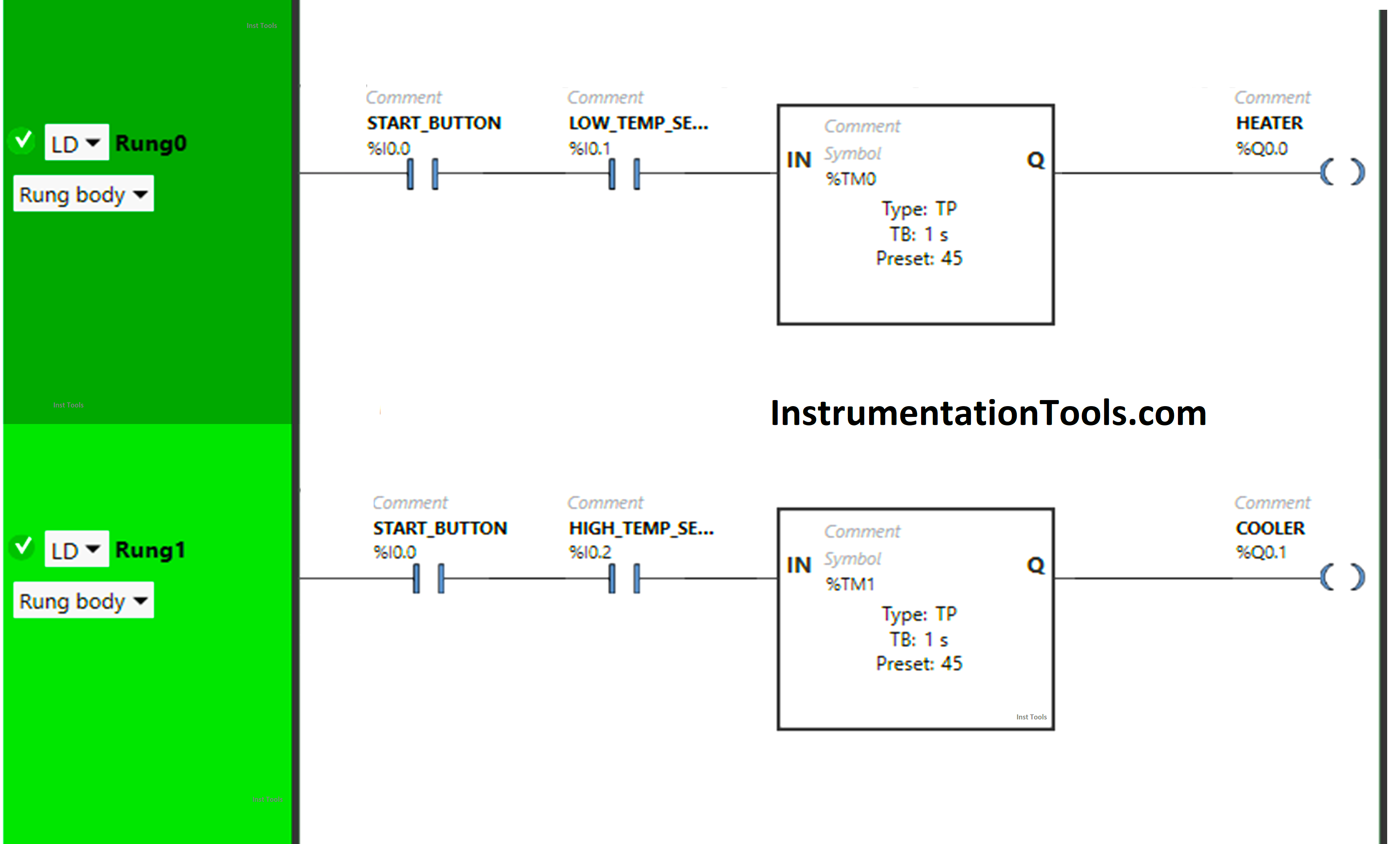
Basic PLC Exercise on Heater and Cooler for Students

Program Description

We have used Normally Open Contact for the Start Button(I0.0), Low-Temperature Sensor (I0.1), and High-Temperature Sensor (Q0.2).

In Rung 0:

  1. Normally Open Contact is used for Start Button (I0.0) and Low Temperature Sensor (I0.1) to turn ON the output Heater (Q0.0).
  2. Timer-type TP is used to Turn ON the output Heater (Q0.0) for a limited time.

In Rung 1:

  1. Normally Open Contact is used for the Start Button (I0.0) and High Temperature Sensor (I0.2) to turn ON the output Cooler (Q0.1).
  2. Timer-type TP is used to Turn ON the output Cooler (Q0.1) for a limited time.

Program Simulation Results

We simulated our PLC program and analyze the results.

Rung 0:
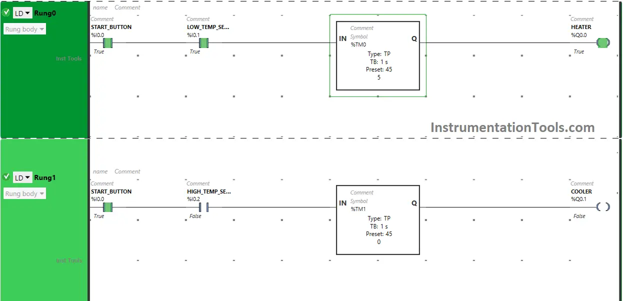
Heating and cooling Ladder Logic

When the Start Button (I0.0) is turned ON and the Low-Temperature sensor (I0.1) gets activated, the signal will flow through the Start Button (I0.0) and Low-Temperature Sensor (I0.1) as Normally Open Contact is used for the Start Button (I0.0) and Low-Temperature Sensor (I0.1).
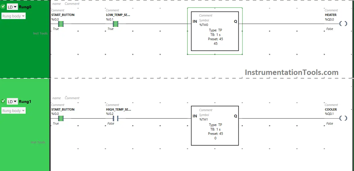
Temperature Control Systems PLC Logic

The output Heater (Q0.0) turns ON for 45 seconds because Timer Function Block type TP is used to turn ON the output Heater (Q0.0) for a limited time and the time is set to 45 seconds. After 45 seconds, the output Heater (Q0.0) will turn OFF.

Rung 1:
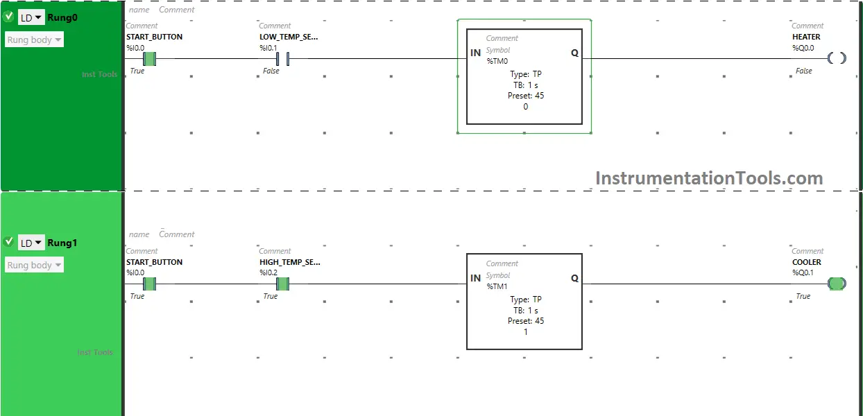
High Temperature Sensor PLC Program

When the Start Button (I0.0) is turned ON and the High-Temperature sensor (I0.2) gets activated, the signal will flow through the Start Button (I0.0) and High-Temperature Sensor (I0.2) as Normally Open Contact is used for the Start Button (I0.0) and High-Temperature Sensor (I0.2).
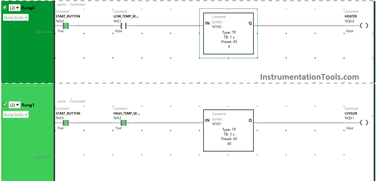
Low Temperature Sensor PLC Programming

The output Cooler (Q0.1) turns ON for 45 seconds because Timer Function Block type TP is used to turn ON the output Cooler (Q0.1) for a limited time and the time is set to 45 seconds. After 45 seconds, the output Cooler (Q0.1)  will turn OFF.

If you liked this article, please subscribe to our YouTube Channel for PLC and SCADA video tutorials.

You can also follow us on Facebook and Twitter to receive daily updates.

Read Next:

  • PLC Program with 5-Second Floor Stops
  • PLC Programming for Barrier Control
  • Traffic Lights PLC Logic using Timers
  • PLC Logic for Water Pumping System
  • PLC Conveyor Forward and Reverse
Don't Miss Our Updates
Be the first to get exclusive content straight to your email.
We promise not to spam you. You can unsubscribe at any time.
Invalid email address
You've successfully subscribed !

Continue Reading

DeMorgan’s Theorems using Ladder Diagram
How to Add Unspecified CPU in Tia Portal?
How to Create New Project Using Simatic Manager
What are Functions in PLC Programming? (FCs)
Best Practices of PLC Wiring – Programmable Logic Controller
Difference Between Microcontroller and PLC
Share This Article
Facebook Whatsapp Whatsapp LinkedIn Copy Link
Share
2 Comments
  • Ruel C. Mabaga says:
    July 9, 2024 at 2:00 pm

    It’s very useful specially for the beginner.

    Reply
  • Ruel C. Mabaga says:
    July 9, 2024 at 2:01 pm

    Interesting

    Reply

Leave a Reply Cancel reply

Your email address will not be published. Required fields are marked *

Stay Connected

128.3kFollowersLike
69.1kFollowersFollow
210kSubscribersSubscribe
38kFollowersFollow

Categories

Explore More

XG5000 PLC Programming for Automatic Exhaust Fan
Examples of SCADA and PLC Configuration Systems
Down Counter PLC Program
PLC Programming Best Practices and Tips
How to Install GSD File in Step 7 PLC using Simatic Manager?
How to Code a FIFO Queue in STL Language in Siemens PLC?
What is a Wet Contact? – Basics of PLC Wiring
Augmented Reality and Virtual Reality in Industrial Automation

Keep Learning

PLC Program for Analog Input Sampling

PLC Analog Input Sampling Ladder Logic

Understanding the Scan Cycle of SIEMENS PLC

Understanding the Scan Cycle of SIEMENS PLC

PLC Ladder Logic for Lube Oil Pump Motor

PLC Ladder Logic for Lube Oil Pump Motor

Energy Meter Data in PLC using Modbus Communication

Modbus Communication between PLC and Energy Meter

PLC Program using One Shot Rising Instructions

One Shot Rising and One Shot Falling Instructions in PLC

Extended Timer Logic in PLC

Extended Timer Logic in PLC

Types of Digital Outputs in PLC

Types of Digital Outputs in PLC

Comparison of Control Loops - Open, Closed, Cascade, Feedforward, Ratio

Comparison of Control Loops – Open, Closed, Cascade, Feedforward, Ratio

Learn More

Automatic Box Filling System using PLC Programming

Automatic Box Filling System using PLC Programming

Single-beam non-dispersive analyzer

Single-beam Non-dispersive Analyzer

Home Automation Project Ideas

Best Home Automation Project Ideas for Engineering Students

Troubleshooting Pump Control Circuit

Troubleshooting Pump Control Circuit

Pressure gauges with capsule elements

Pressure Gauges with Capsule Sensor Principle

SCADA Features

Features of SCADA

Dip Tube Type Level System

Questions on Dip Tube Type Level System

Closed Tank Level Measurement using DP Transmitter

Cat and Mouse type Level Indicator

Menu

  • About
  • Privacy Policy
  • Copyright

Quick Links

  • Learn PLC
  • Helping Hand
  • Part Time Job

YouTube Subscribe

Follow US
All rights reserved. Reproduction in whole or in part without written permission is prohibited.
Welcome Back!

Sign in to your account

Username or Email Address
Password

Lost your password?