A counter is a PLC instruction that either increments (counts up) or decrements (counts down) an integer number value when prompted by the transition of a bit from 0 to 1 (“false” to “true”).
Counter instructions come in three basic types:
- up counters,
- down counters, and
- up/down counters.
Both “up” and “down” counter instructions have single inputs for triggering counts, whereas “up/down” counters have two trigger inputs: one to make the counter increment and one to make the counter decrement.
PLC Counter Instructions
To illustrate the use of a counter instruction, we will analyze a PLC-based system designed to count objects as they pass down a conveyor belt:

In this system, a continuous (unbroken) light beam causes the light sensor to close its output contact, energizing discrete channel IN4.
When an object on the conveyor belt interrupts the light beam from source to sensor, the sensor’s contact opens, interrupting power to input IN4.
A push-button switch connected to activate discrete input IN5 when pressed will serve as a manual “reset” of the count value.
An indicator lamp connected to one of the discrete output channels will serve as an indicator of when the object count value has exceeded some pre-set limit.
We will now analyze a simple Ladder Diagram program designed to increment a counter instruction each time the light beam breaks:

This particular counter instruction (CTU) is an incrementing counter, which means it counts “up” with each off-to-on transition input to its “CU” input.
The normally-closed virtual contact (IN sensor object) is typically held in the “open” state when the light beam is continuous, by virtue of the fact the sensor holds that discrete input channel energized while the beam is continuous.
When the beam is broken by a passing object on the conveyor belt, the input channel de-energizes, causing the virtual contact IN sensor object to “close” and send virtual power to the “CU” input of the counter instruction.
This increments the counter just as the leading edge of the object breaks the beam. The second input of the counter instruction box (“R”) is the reset input, receiving virtual power from the contact IN switch reset whenever the reset pushbutton is pressed. If this input is activated, the counter immediately resets its current value (CV) to zero.
Also Read : PLC Timer Instructions
Status indication is shown in this Ladder Diagram program, with the counter’s preset value (PV) of 25 and the counter’s current value (CV) of 0 shown highlighted in blue.
The preset value is something programmed into the counter instruction before the system put into service, and it serves as a threshold for activating the counter’s output (Q), which in this case turns on the count indicator lamp (the OUT counts reached coil).
According to the IEC 61131-3 programming standard, this counter output should activate whenever the current value is equal to or greater than the preset value (Q is active if CV ≥ PV).
This is the status of the same program after thirty objects have passed by the sensor on the conveyor belt.
As you can see, the current value of the counter has increased to 30, exceeding the preset value and activating the discrete output:

If all we did not care about maintaining an accurate total count of objects past 25 – but merely wished the program to indicate when 25 objects had passed by.
we could also use a down counter instruction preset to a value of 25, which turns on an output coil when the count reaches zero:

Here, a “load” input causes the counter’s current value to equal the preset value (25) when activated.
With each sensor pulse received, the counter instruction decrements. When it reaches zero, the Q output activates.
A potential problem in either version of this object-counting system is that the PLC cannot discriminate between forward and reverse motion on the conveyor belt.
If, for instance, the conveyor belt were ever reversed in direction, the sensor would continue to count objects that had already passed by before (in the forward direction) as those objects retreated on the belt.
This would be a problem because the system would “think” more objects had passed along the belt (indicating greater production) than actually did.
Also Read : PLC Math Instructions
One solution to this problem is to use an up/down counter, capable of both incrementing (counting up) and decrementing (counting down), and equip this counter with two light-beam sensors capable of determining direction of travel.
If two light beams are oriented parallel to each other, closer than the width of the narrowest object passing along the conveyor belt, we will have enough information to determine direction of object travel:

This is called quadrature signal timing, because the two pulse waveforms are approximately 90 deg (one-quarter of a period) apart in phase.
We can use these two phase-shifted signals to increment or decrement an up/down counter instruction, depending on which pulse leads and which pulse lags.
A Ladder Diagram PLC program designed to interpret the quadrature pulse signals is shown here, making use of negative-transition contacts as well as standard contacts:
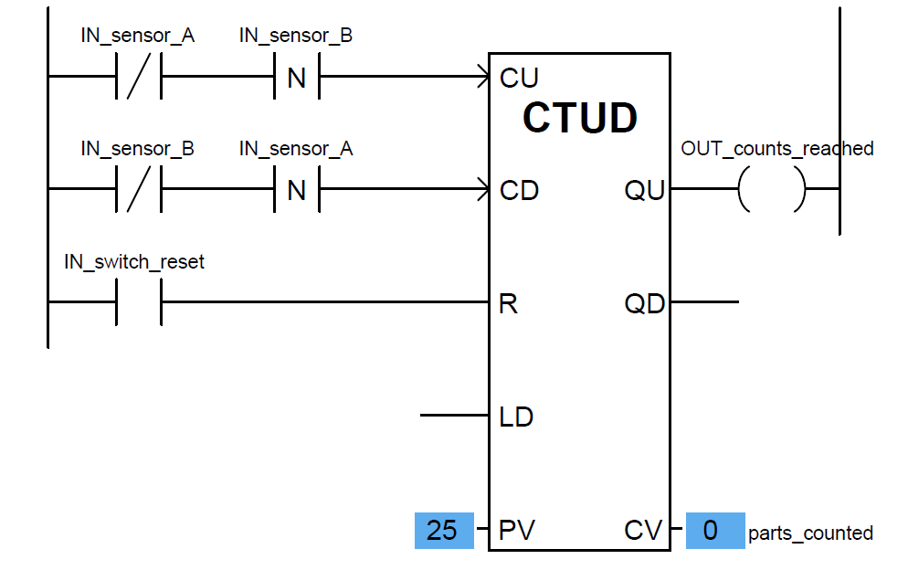
The counter will increment (count up) when sensor B de-energizes only if sensor A is already in the de-energized state (i.e. light beam A breaks before B).
Counter will decrement (count down) when sensor A de-energizes only if sensor B is already in the de-energized state (i.e. light beam B breaks before A).
Note that the up/down counter has both a “reset” (R) input and a “load” input (“LD”) to force the current value.
Activating the reset input forces the counter’s current value (CV) to zero, just as we saw with the “up” counter instruction.
Then Activating the load input forces the counter’s current value to the preset value (PV), just as we saw with the “down” counter instruction.
In the case of an up/down counter, there are two Q outputs: a QU (output up) to indicate when the current value is equal to or greater than the preset value, and a QD (output down) to indicate when the current value is equal to or less than zero.
Note how the current value (CV) of each counter shown is associated with a tag name of its own, in this case parts counted.
The integer number of a counter’s current value (CV) is a variable in the PLC’s memory just like boolean values such as IN sensor A and IN switch reset, and may be associated with a tag name or symbolic address just the same.
This allows other instructions in a PLC program to read (and sometimes write!) values from and to that memory location.
Credits : by Tony R. Kuphaldt – Creative Commons Attribution 4.0 License
PLC Tutorials :
What is Programmable Logic Controller ?
What is Ladder Diagram Programming ?
History of Programmable Logic Controllers
Mis-conceptions of PLC Ladder Logic
Contacts and coils in PLC
Digital Input and Output Modules
Analog I/O and Network I/O
PLC Input/Output Modules
Memory Mapping in PLC
Analog Input Scaling
PLC Example with Switches
Counter Instructions
Timer Instructions
Math instructions
Data Instructions
Ladder Logic Questions
If you liked this article, then please subscribe to our YouTube Channel for PLC and SCADA video tutorials.
You can also follow us on Facebook and Twitter to receive daily updates.


Will be fair to mention the source where the information was copied from: credits, Tony Kuphaldt
Hmmm, few articles missed the credits. Added. Thank You.