A PLC connection represents the signal flow starting from the field transmitters, junction box, marshalling cabinet, system cabinet and Human-Machine Interface for the operator graphic display.
PLC Connection

Here we are discussing about traditional 4-20mA analog input devices only for ease of understanding the basic concept.
PLC or DCS Signal Flow :

We have thousands of field transmitters installed in a process plant. So it is practically difficult to lay straight individual cables from each field transmitter to control room for displaying the process variables on the workstation.
As per design standards, particular number of field devices / transmitters are wired and terminated in a Field Junction box.
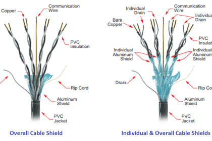
Cable used for connecting the field device to Junction box are called as Branch cables or field cables. Generally we use one pair cables for branch cables.
The below figure shows 5 field devices are connected to a Junction Box using individual Branch cables.
In this example, for carrying out these five signals to control room we need minimum 5 pair cable (means one cable have 5 pairs) and also we have to consider spare cable requirement for future purpose.
so at least 6 pair cable or better a 12 pair cable best suits the below requirement.
Say we choose 12 pair cable and is nothing but a Main Cable or Home run cable as it interfaces the field junction box and marshalling cabinet in the control room.
so finally one big main cable is required and serves our purpose.
Field Instruments to Junction box

In a Process plant, we have so many Junction boxes installed and connected with number of field devices.
Say we have 100 no’s of Junction boxes installed that means we have 100 no’s main cables are there which are coming from field to control room.
so practically it not possible to directly wire these main cables to analog input/output cards. To avoid these problems we use Marshalling cabinet for terminating these 100 no’s main cables.
Marshalling cabinet main purpose is to provide main cables termination and then re-distribute the field devices to respective Analog Input/Output card using internal wiring.
Internal wiring will be used to connect from Marshalling cabinet to system cabinet.
Wiring between Marshalling and System Cabinets

System cabinet consists of Processor card (CPU), Analog Input Cards, Analog Output Cards, Communication cards etc.
Once Main cables are terminated in Marshalling cabinet, we have to take these field devices to the respective Analog input card channel.
so we use internal wiring to route these main cables/field devices from marshalling to system cabinet.
Once the main cables are connected to the Analog Input card via internal wiring and it converts the 4-20mA which is coming from field devices into equivalent Digital signal i.e. in Binary codes and the same will be communicated to Processor card.
The processor card performs as per the predefined or programmed instructions. The processor card may have inbuilt or separate Ethernet communication link which is used to display the measured process variables on the workstation.
Summary
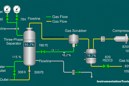
The above animation depicts a typical cabling scheme that collects and distributes signals to and from the field devices.
A Field Junction Box is used to concentrate the signals into multi-conductor homerun cables or main cables.
The homerun cables then terminate in a remote or marshalling cabinet where the signals are marshalled (reorganized) as necessary to efficiently terminate at the I/O interface of the DCS or PLC system.
If you liked this article, then please subscribe to our YouTube Channel for PLC and SCADA video tutorials.
You can also follow us on Facebook and Twitter to receive daily updates.
Read Next:


It helps me a lot..Im just a beginner and need something like this,,,,thanks for posting
Nice
Thanks brother
Thanks
Nice knowledge site
Nice one
Best site ever seen. Nice collection
How to do internal cross wiring for marshalling cabinet? please explain with animation or pics?
Thanks a lot. It really helps me a lot to understand the basics. The Best Website for Inst Guys.
Ji super keep it up
is it true?
that fieldbus can omit marshaling cabinet
Wow thank allah it’s great web
Thanks for helping
thanks!
thanks a lot
Thank you very much
Verry use full knowledge
Thanks Brother
Very good knowledge
Great information for new one