Inst ToolsInst ToolsInst Tools
  • Courses
  • Automation
    • PLC
    • Control System
    • Safety System
    • Communication
    • Fire & Gas System
  • Instrumentation
    • Design
    • Pressure
    • Temperature
    • Flow
    • Level
    • Vibration
    • Analyzer
    • Control Valve
    • Switch
    • Calibration
    • Erection & Commissioning
  • Interview
    • Instrumentation
    • Electrical
    • Electronics
    • Practical
  • Q&A
    • Instrumentation
    • Control System
    • Electrical
    • Electronics
    • Analog Electronics
    • Digital Electronics
    • Power Electronics
    • Microprocessor
  • Request
Search
  • Books
  • Software
  • Projects
  • Process
  • Tools
  • Basics
  • Formula
  • Power Plant
  • Root Cause Analysis
  • Electrical Basics
  • Animation
  • Standards
  • 4-20 mA Course
  • Siemens PLC Course
Reading: PLC Analog I/O and Network I/O
Share
Font ResizerAa
Inst ToolsInst Tools
Font ResizerAa
  • Courses
  • Design
  • PLC
  • Interview
  • Control System
Search
  • Courses
  • Automation
    • PLC
    • Control System
    • Safety System
    • Communication
    • Fire & Gas System
  • Instrumentation
    • Design
    • Pressure
    • Temperature
    • Flow
    • Level
    • Vibration
    • Analyzer
    • Control Valve
    • Switch
    • Calibration
    • Erection & Commissioning
  • Interview
    • Instrumentation
    • Electrical
    • Electronics
    • Practical
  • Q&A
    • Instrumentation
    • Control System
    • Electrical
    • Electronics
    • Analog Electronics
    • Digital Electronics
    • Power Electronics
    • Microprocessor
  • Request
Follow US
All rights reserved. Reproduction in whole or in part without written permission is prohibited.
Inst Tools > Blog > PLC Tutorials > PLC Analog I/O and Network I/O

PLC Analog I/O and Network I/O

Last updated: March 4, 2021 4:56 pm
Editorial Staff
PLC Tutorials
No Comments
Share
3 Min Read
SHARE

In the early days of programmable logic controllers, processor speed and memory were too limited to support anything but discrete (on/off) control functions.

Contents
PLC Analog I/OPLC Network I/O

Consequently, the only I/O capability found on early PLCs were discrete in nature. Modern PLC technology, though, is powerful enough to support the measurement, processing, and output of analog (continuously variable) signals.

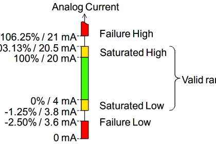
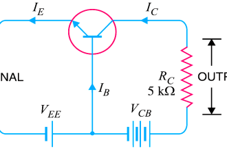
All PLCs are digital devices at heart. Thus, in order to interface with an analog sensor or control device, some “translation” is necessary between the analog and digital worlds. Inside every analog input module is an ADC, or Analog-to-Digital Converter, circuit designed to convert an analog electrical signal into a multi-bit binary word.

Conversely, every analog output module contains a DAC, or Digital-to-Analog Converter, circuit to convert the PLC’s digital command words into analog electrical quantities.

Analog I/O is commonly available for modular PLCs for many different analog signal types, including:

  • Voltage (0 to 10 volt, 0 to 5 volt)
  • Current (0 to 20 mA, 4 to 20 mA)
  • Thermocouple (millivoltage)
  • RTD
  • Strain gauge

PLC Analog I/O

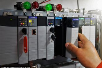
The following photographs show two analog I/O cards for an Allen-Bradley SLC 500 modular PLC system, an analog input card and an analog output card. Labels on the terminal cover doors indicate screw terminal assignments:

PLC analog output card

PLC Network I/O

Many different digital network standards exist for PLCs to communicate with, from PLC to PLC and between PLCs and field devices.

One of the earliest digital protocols developed for PLC communication was Modbus, originally for the Modicon brand of PLC.

Modbus was adopted by other PLC and industrial device manufacturers as a de facto standard, and remains perhaps the most universal digital protocol available for industrial digital devices today.

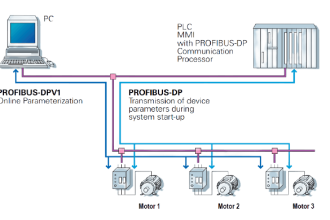
Another digital network standard developed by a particular manufacturer and later adopted as a de facto standard is Profibus, originally developed by Siemens.

Credits : by Tony R. Kuphaldt

PLC Tutorials :

  • What is Programmable Logic Controller  ?
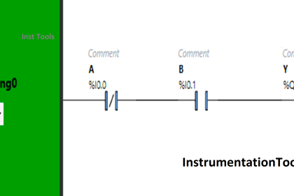
  • What is Ladder Diagram Programming ?
  • History of Programmable Logic Controllers
  • Mis-conceptions of PLC Ladder Logic
  • Contacts and coils in PLC
  • Digital Input and Output Modules
  • Analog I/O and Network I/O
  • PLC Input/Output Modules
  • Memory Mapping in PLC
  • Analog Input Scaling
  • PLC Example with Switches
  • Counter Instructions
  • Timer Instructions
  • Math instructions
  • Data Instructions
  • Ladder Logic Questions

If you liked this article, then please subscribe to our YouTube Channel for PLC and SCADA video tutorials.

You can also follow us on Facebook and Twitter to receive daily updates.

Don't Miss Our Updates
Be the first to get exclusive content straight to your email.
We promise not to spam you. You can unsubscribe at any time.
Invalid email address
You've successfully subscribed !

Continue Reading

PLC Compressor Control Ladder Logic
PLC Valve Control Ladder Logic Programming
PLC Counters Program
The Concept of Shift Register in Omron PLC with Example
Open Platform Communication (OPC)
How to Troubleshoot a PLC System?
Share This Article
Facebook Whatsapp Whatsapp LinkedIn Copy Link
Share
Leave a Comment

Leave a Reply Cancel reply

Your email address will not be published. Required fields are marked *

Stay Connected

128.3kFollowersLike
69.1kFollowersFollow
210kSubscribersSubscribe
38kFollowersFollow

Categories

Explore More

Retentive ON Delay Timer using PLC
How to Communicate with Excel from Intouch SCADA?
PLC Program for Artificial Fishpond Water Level Monitoring System
SCADA Interview Questions and Answers
I&C Engineer Roles & Responsibilities – Instrumentation Design
Difference between Power Cables and Signal Cables
Basics of Loop Checks
How to Configure Distributed IO in a PLC Project?

Keep Learning

Boolean Logic to PLC Programming

Boolean Logic to PLC Programming

HMI Screen Design for Hazardous Applications

HMI Screen Design for Hazardous Applications

PLC Program for Positive edge pulse output for one scan cycle

PLC Program for Positive Edge Pulse Output for One Scan Cycle

Learn PLC Programming

Basics of Ladder Diagram in PLC Programming

Transmitters 4-20mA Current Failure Alarm Limits

Transmitters 4-20mA Current Failure Alarm Limits

Automatic Car Washing Process using PLC Ladder Diagram

Automatic Car Washing using PLC

PLC offline data of a project are compared

Compare Two Offline PLC Projects

JMP instruction in PLC Programming

How to use JUMP Instruction in PLC Ladder Logic?

Learn More

On Off Valve Root Cause Analysis

Root Cause Analysis for FRP Line Damaged due to On-Off Valve

Intelligent MCC

What is Smart or Intelligent MCC?

Free Download PLC Book

#10 PLC Best Practices – Assign Register Blocks by Function

Tagging Philosophy for Junction Box

Tagging Philosophy for Junction Box, Cable, and Cable Drum

Transistor as Amplifier

Transistor as Amplifier

Rotary Drier Shell to Split Gear drive

Rotary Drier Shell to Split Gear drive eliminates too frequent drive failures

Tuning a Liquid Level Process Control Loop - 1

Tuning a Liquid Level Process Control Loop

Differences between Watts and Volt Amps

Differences between Watts and Volt Amps

Menu

  • About
  • Privacy Policy
  • Copyright

Quick Links

  • Learn PLC
  • Helping Hand
  • Part Time Job

YouTube Subscribe

Follow US
All rights reserved. Reproduction in whole or in part without written permission is prohibited.
Welcome Back!

Sign in to your account

Username or Email Address
Password

Lost your password?