Inst ToolsInst ToolsInst Tools
  • Courses
  • Automation
    • PLC
    • Control System
    • Safety System
    • Communication
    • Fire & Gas System
  • Instrumentation
    • Design
    • Pressure
    • Temperature
    • Flow
    • Level
    • Vibration
    • Analyzer
    • Control Valve
    • Switch
    • Calibration
    • Erection & Commissioning
  • Interview
    • Instrumentation
    • Electrical
    • Electronics
    • Practical
  • Q&A
    • Instrumentation
    • Control System
    • Electrical
    • Electronics
    • Analog Electronics
    • Digital Electronics
    • Power Electronics
    • Microprocessor
  • Request
Search
  • Books
  • Software
  • Projects
  • Process
  • Tools
  • Basics
  • Formula
  • Power Plant
  • Root Cause Analysis
  • Electrical Basics
  • Animation
  • Standards
  • 4-20 mA Course
  • Siemens PLC Course
Reading: Playground Swing Logic Exercise Program in PLC
Share
Font ResizerAa
Inst ToolsInst Tools
Font ResizerAa
  • Courses
  • Design
  • PLC
  • Interview
  • Control System
Search
  • Courses
  • Automation
    • PLC
    • Control System
    • Safety System
    • Communication
    • Fire & Gas System
  • Instrumentation
    • Design
    • Pressure
    • Temperature
    • Flow
    • Level
    • Vibration
    • Analyzer
    • Control Valve
    • Switch
    • Calibration
    • Erection & Commissioning
  • Interview
    • Instrumentation
    • Electrical
    • Electronics
    • Practical
  • Q&A
    • Instrumentation
    • Control System
    • Electrical
    • Electronics
    • Analog Electronics
    • Digital Electronics
    • Power Electronics
    • Microprocessor
  • Request
Follow US
All rights reserved. Reproduction in whole or in part without written permission is prohibited.
Inst Tools > Blog > PLC Tutorials > Playground Swing Logic Exercise Program in PLC

Playground Swing Logic Exercise Program in PLC

In Playground Swing Logic, a timer should count down from 30 seconds when a child starts Swinging. An Alarm activates after time is up.

Last updated: May 20, 2024 10:44 am
Editorial Staff
PLC Tutorials
2 Comments
Share
5 Min Read
SHARE

In Playground Swing Logic, a timer should count down from 30 seconds when a child starts Swinging. An Alarm activates after time is up.

Contents
Playground Swing LogicPLC Basics for StudentsInputs and OutputsProgram in PLCExplanationSimulation ResultsWhen the Start Button is turned ON (Child Starts Swinging)When the Reset Button is Pressed and Released

Note: This PLC program was created for the persons to learn the PLC basics.

Playground Swing Logic

Problem Statement

Design a PLC ladder logic for the following application.

We are using one toggle switch and one Push Button to control the Alarm.

When a child starts Swinging, a timer should count down from 30 seconds. An Alarm should sound when the time is up.

A Reset Button will start the countdown again.

PLC Basics for Students

Instrumentation Tools provides the PLC basics with simple problems and solutions for students.

This video explains swing example programming using ladder logic.

Programming Example in PLC - Playground Swing Timer

Inputs and Outputs

Digital Inputs:

Start Button: I0.0

Reset Button: I0.1

Digital Outputs:

Alarm: Q0.0

Program in PLC
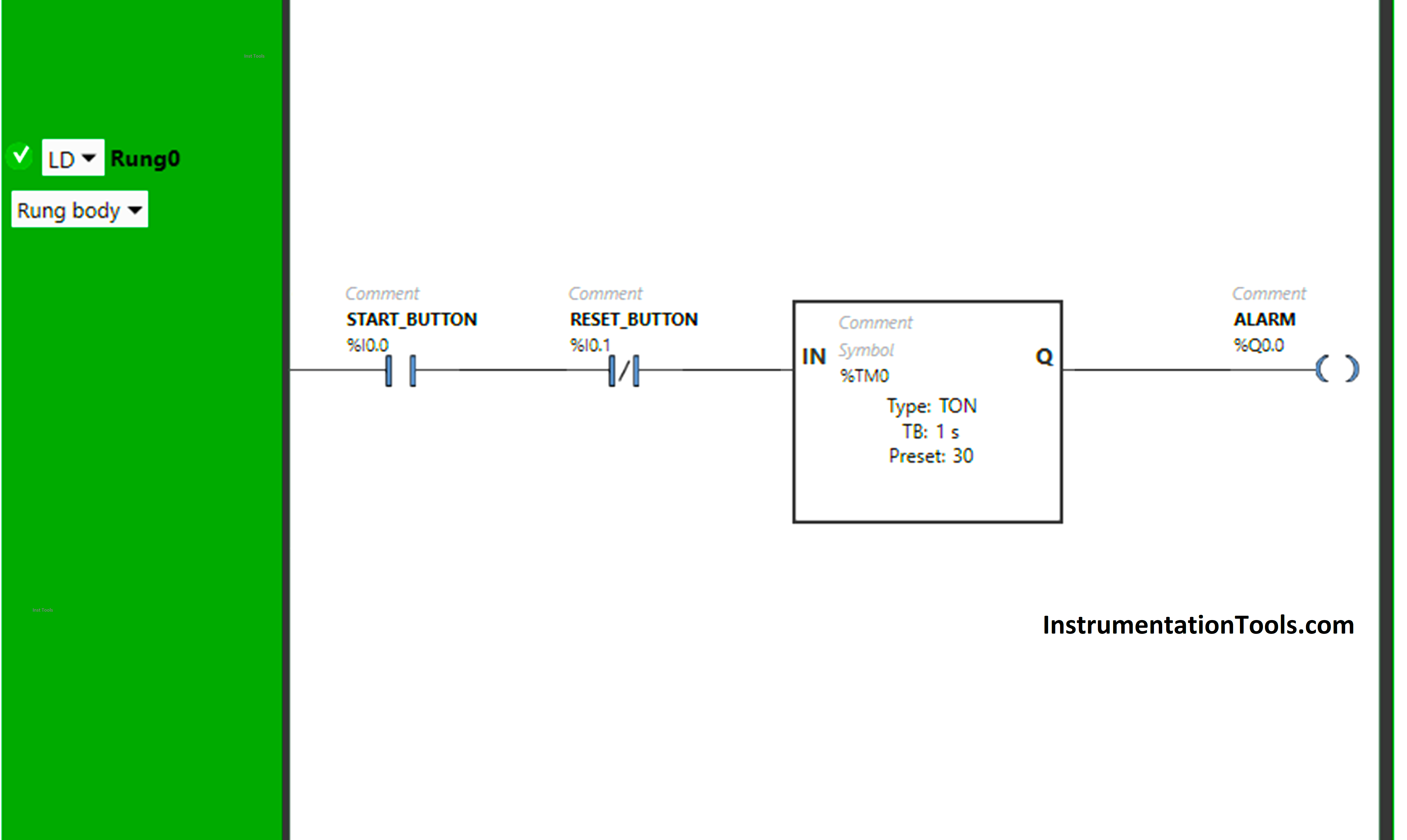
Playground Swing Logic Exercise Program in PLC

Explanation

We have used Normally Open Contact for the Start Button (I0.0).

We have used Normally Closed Contact for the Reset Button (I0.1).

In Rung 0:

  1. Normally Open Contact is used for the Start Button (I0.0) to Turn ON the output Alarm (Q0.0)
  2.  Timer TON is used to delay the turning ON time of the output Alarm (Q0.0) for some time.
  3. Normally Closed Contact is used for Reset Button (I0.1) to turn OFF the output Alarm (Q0.0) and restart the timer.

When the Start Button (I0.0) is turned ON or (child starts swinging), the output Alarm (Q0.0) will turn ON after 30 seconds as Timer Function Block TON is used to delay the turning ON time of the output Alarm (Q0.0). The time is set to 30 seconds.

In a false state, Normally Closed Contact used for the Reset Button (I0.1) passes the signal to turn ON the output Alarm (Q0.0). After 30 seconds, the output Alarm (Q0.0) will turn ON.

When Reset Button (I0.1) is pressed and released, the output Alarm (Q0.0) will turn OFF because When the Reset Button (I0.1) is pressed, Normally Closed Contact used for Reset Button (I0.0) will be in True state and does not allow the signal to pass through it and the output Alarm (Q0.0) will turn OFF.

When the Reset Button is released (I0.1), Normally Closed Contact used for the Reset Button (I0.0) will be in a false state and allow the signal to pass through it. Then, the timer again starts in the Timer Function Block type TON. The time is set to 30 seconds. After 30 seconds, the output Alarm (Q0.0) will turn ON again.

Simulation Results

Now we simulate our PLC program and discuss the results.

When the Start Button is turned ON (Child Starts Swinging)

When the Start Button (I0.0) is turned ON or (child starts swinging), the output Alarm (Q0.0) will turn ON after 30 seconds as Timer Function Block TON is used to delay the turning ON time of the output Alarm (Q0.0).

The time is set to 30 seconds.

Logic Program in PLC

In a false state, Normally Closed Contact used for the Reset Button (I0.1) passes the signal to turn ON the output Alarm (Q0.0).

After 30 seconds, the output Alarm (Q0.0) will turn ON.

swing plc logic tutorial

When the Reset Button is Pressed and Released

When the Reset Button (I0.1) is pressed and released, the output Alarm (Q0.0) will turn OFF because When the Reset Button (I0.1) is pressed.

Normally Closed Contact used for the Reset Button (I0.0) will be in a True state and does not allow the signal to pass through it and the output Alarm (Q0.0) will turn OFF.

Exercise Program in PLC for Students

When the Reset Button is released (I0.1), Normally Closed Contact used for the Reset Button (I0.0) will be in a false state and allow the signal to pass through it.

Then, the timer again starts in the Timer Function Block type TON. The time is set to 30 seconds. After 30 seconds, the output Alarm (Q0.0) will turn ON again.

PLC exercise programs for students

If you liked this article, please subscribe to our YouTube Channel for PLC and SCADA video tutorials.

You can also follow us on Facebook and Twitter to receive daily updates.

Read Next:

  • Traffic Lights PLC Program using Timers
  • Heater and Cooler PLC Exercise Problem
  • PLC Applications Examples of Door Lock
  • Door Lock with Delay PLC Exercise Problem
  • PLC Emergency Stop Example Programming
Don't Miss Our Updates
Be the first to get exclusive content straight to your email.
We promise not to spam you. You can unsubscribe at any time.
Invalid email address
You've successfully subscribed !

Continue Reading

Open Loop and Closed Loop System Questions Answers
FactoryTalk Studio and SQL Server for Data Logging
Auto Sugar Bag Filling Station
Sorting & Distribution Line PLC Programming – Advanced Logic
PLC Trainer Demo Download
Free Omron PLC Programming Course in HINDI
Share This Article
Facebook Whatsapp Whatsapp LinkedIn Copy Link
Share
2 Comments
  • Biplab Newar says:
    July 18, 2024 at 1:57 am

    Hello sir, how do I get a PLC programmer certificate?

    Reply
    • Editorial Staff says:
      July 18, 2024 at 9:45 am

      Join Here – https://learn.automationcommunity.com/courses/

      Reply

Leave a Reply Cancel reply

Your email address will not be published. Required fields are marked *

Stay Connected

128.3kFollowersLike
69.1kFollowersFollow
210kSubscribersSubscribe
38kFollowersFollow

Categories

Explore More

Components of PLC
How to Connect PLC with SCADA System via OPC UA?
What is Contextual HMI? – HMI Screens on a Mobile or Tablet
Why Use a Current Loop?
Types of Instructions in PLC Programming
PLC Automatic Irrigation System
ICS System Design Considerations
How to Train Your Maintenance Team for Industrial Automation Systems?

Keep Learning

Coil Type Timers in Siemens PLC Programming

Coil Type Timers in Siemens PLC Programming

Industrial Automation Solution

How to Choose the Right Industrial Automation Solution?

Motion Detection based Street Light PLC Logic Solution

Motion Detection based Street Light: PLC Logic Solution

Quiz on Electrical Meters and Measurement

200+ Quiz on Electrical Meters, Measurement, and Troubleshooting

Yokogawa DCS

Yokogawa DCS and SIS System Architecture

Automatic Car Door Simulation

Automatic Door Operation PLC Programming and Simulation

OPC Server

What is the OPC Server?

How to Program Sequential Outputs in PLC

Timer-Based Sequential PLC Program with One Button

Learn More

How to Identify Phase, Earth, and Neutral Wires_

How to Identify Phase, Earth, and Neutral Wires?

Level Measurement in Liquids

Point Level Detection Working Principle

Direct & reverse actions control valve

Direct Acting Control Valves & Reverse Acting Control Valves

Example PLC Program to Control a Pump based on Level Sensors

Example PLC Program to Control a Pump based on Level Sensors

Differential Pressure Transmitter Zero Suppression

Basics of DP Transmitter Suppression and Elevation

Career Scope in Mechanical Engineering

Career Scope in Mechanical Engineering

SCL Language in Siemens Tia Portal

FOR DO Statement in SCL Language

Digital Image Processing Projects - DIP Project Ideas

600+ Digital Image Processing Projects – DIP Project Ideas

Menu

  • About
  • Privacy Policy
  • Copyright

Quick Links

  • Learn PLC
  • Helping Hand
  • Part Time Job

YouTube Subscribe

Follow US
All rights reserved. Reproduction in whole or in part without written permission is prohibited.
Welcome Back!

Sign in to your account

Username or Email Address
Password

Lost your password?