This article discusses the implementation of a sequential system concept in a PLC program to turn ON multiple outputs with one input. The system will control the activation of outputs in a specific sequence with predetermined timing using only one button. The system utilizes a data comparison function to manage the transition between program sequences. The compared data can be reset if there is a need to stop the program sequence. There will be three sequences in this program, and when the system reaches the final sequence, it will stop.
Program Objective
Step-by-Step System:
The system is in standby mode when the Start button is pressed.
The sequence transition can be controlled by pressing the Run button.
When the Run button is pressed, the data in the memory word Sequence will increment by 1 (+1).
- When the data value equals “1”, Lamp 1 will turn ON for 4 seconds and then turn OFF.When the data value equals “2”, Lamp 2 will turn ON for 5 seconds and then turn OFF.
- When the data value equals “3”, Lamp 3 will turn ON for 6 seconds and then turn OFF.
- When the data in the memory word Sequence exceeds “3”, the data in the memory word Sequence will reset to zero “0”.
The data in the memory word Sequence will reset to zero “0” when the Reset button is pressed.
One Input to Turn ON Multiple Outputs
IO Mapping
| S.No. | Comment | Input (I) | Output (Q) | Memory Bits | Memory Word | Timers |
|---|---|---|---|---|---|---|
| 1 | START | P0000 | ||||
| 2 | STOP | P0001 | ||||
| 3 | RUN_SYSTEM | P0002 | ||||
| 4 | RESET_SEQUENCE | P0003 | ||||
| 5 | LAMP1 | P0040 | ||||
| 6 | LAMP2 | P0041 | ||||
| 7 | LAMP3 | P0042 | ||||
| 8 | TIMER1 | T000 | ||||
| 9 | TIMER2 | T001 | ||||
| 10 | TIMER3 | T002 | ||||
| 11 | SYSTEM_ON | M1000 | ||||
| 12 | SEQUENCE | M000 |
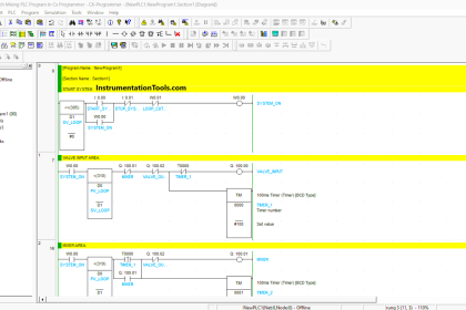
Ladder Logic Solution
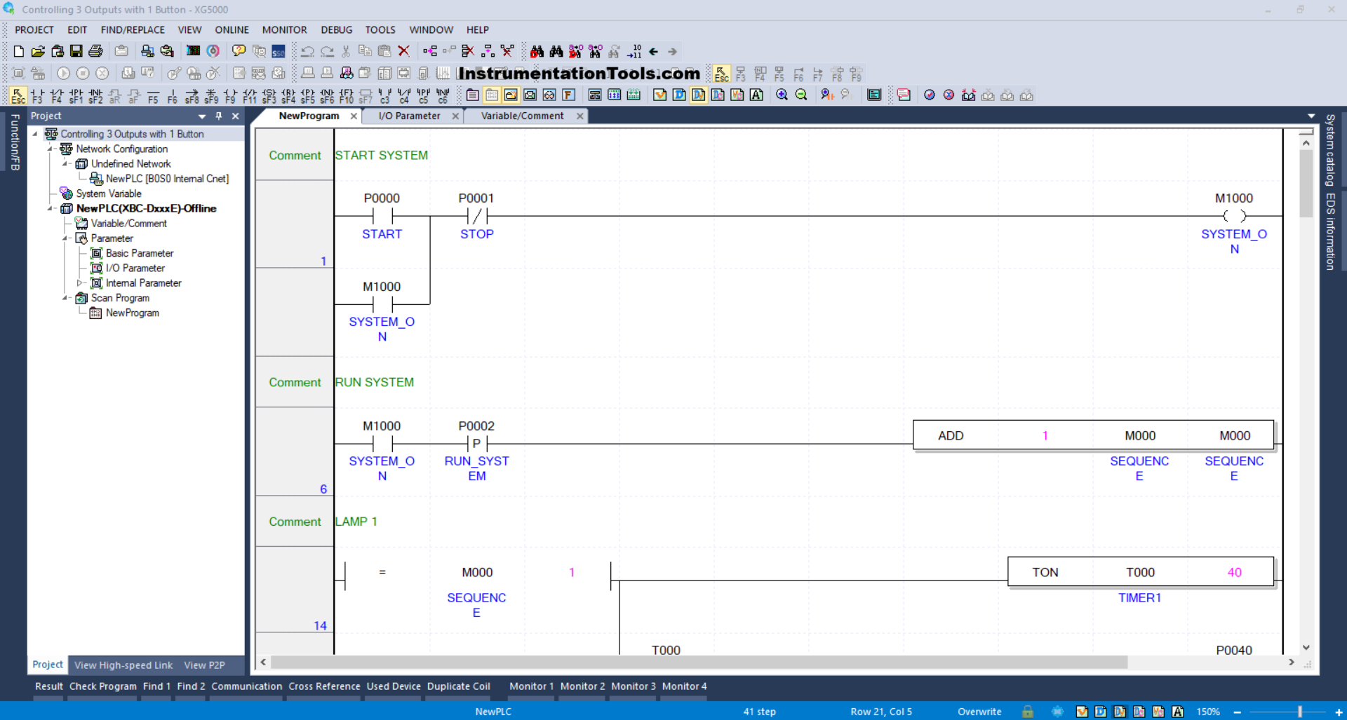
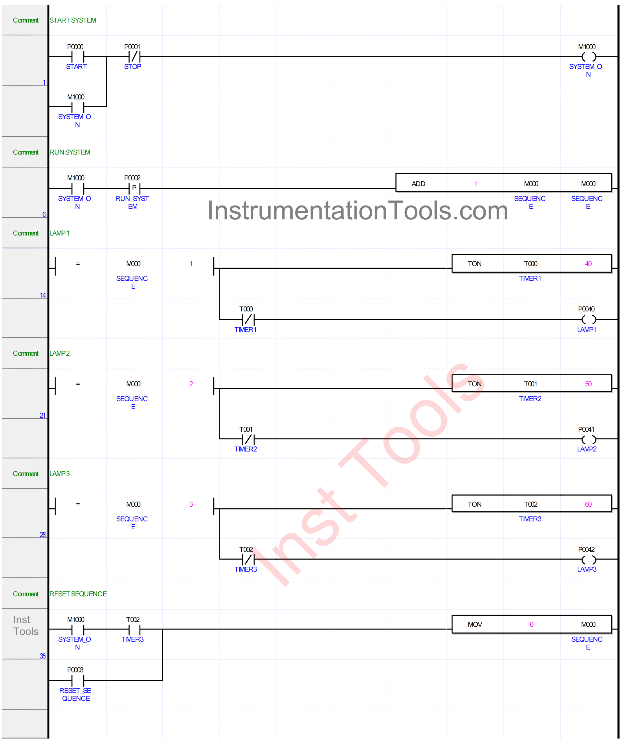
RUNG 1 (START)
In this Rung, when the START (P0000) button is pressed, the memory bit SYSTEM_ON (M1000) changes to a HIGH state. Because it uses Latching, the memory bit SYSTEM_ON (M1000) remains in a HIGH state even though the START (P0000) button has been released.
The memory bit SYSTEM_ON (M1000) will be in a LOW state if the STOP (P0001) button is pressed.
RUNG 6 (RUN_SYSTEM)
When the NO contact of the memory bit SYSTEM_ON (M1000) is in a HIGH state and the RUN_SYSTEM (P0002) button is pressed, the ADD instruction will add data (+1) to the memory word SEQUENCE (M000).
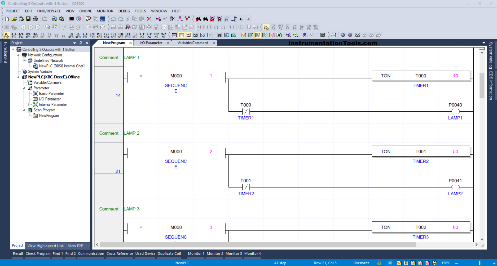
RUNG 14 (LAMP 1)
When the value in the memory word SEQUENCE (M000) is Equal To “1”, the LAMP1 (P0040) output will be ON.
Next, the TIMER1 (T000) timer starts counting up to 4 seconds. When the TIMER1 (T000) timer has finished counting, the LAMP1 (P0040) output becomes OFF due to the Interlock of the TIMER1 (T000) timer.
RUNG 21 (LAMP 2)
When the value in the memory word SEQUENCE (M000) is Equal To “2”, the LAMP2 (P0041) output will be ON.
The TIMER2 (T001) timer starts counting up to 5 seconds. When the TIMER2 (T001) timer has finished counting, the LAMP2 (P0041) output becomes OFF due to the Interlock of the TIMER2 (T001) timer.
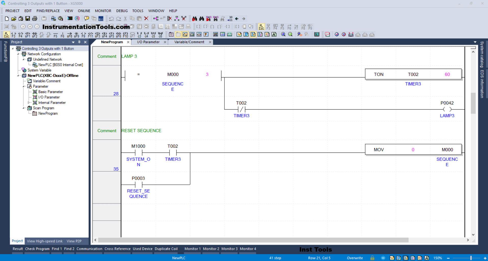
RUNG 28 (LAMP 3)
When the value in the memory word SEQUENCE (M000) is Equal To “3”, the LAMP3 (P0042) output will be ON.
The timer TIMER1 (T002) starts counting up to 6 seconds. When the timer TIMER3 (T002) has finished counting, the LAMP3 (P0042) output becomes OFF due to the Interlock of the timer TIMER3 (T002).
RUNG 35 (RESET SEQUENCE)
In this Rung, when the NO contact of the memory bit SYSTEM_ON (M1000) and the timer TIMER3 (T002) are in the HIGH state, the memory word SEQUENCE (M000) becomes “0”.
The MOV instruction will move the value “0” to the memory word SEQUENCE (M000).
Or, if the RESET_SEQUENCE (P0003) button is pressed, the memory word SEQUENCE (M000) becomes “0”.
Read Next:
- PLC Example of Water Level-Based Pump Control
- Automatic Door Operation PLC Programming
- Sorting & Distribution Line PLC Programming
- How to Take a Backup from a Physical PLC?
- PLC Programming for Defective Parts Sorting