This article will discuss a PLC program for a product delivery system using 4 conveyors with an interlock in Omron CX-Programmer. The system will only activate when it detects a product. Each conveyor will interlock with the one another, causing all conveyors to operate alternately. The system will count the products that have been delivered. An alarm will activate if the system does not detect a product within a certain period.
Program Objective
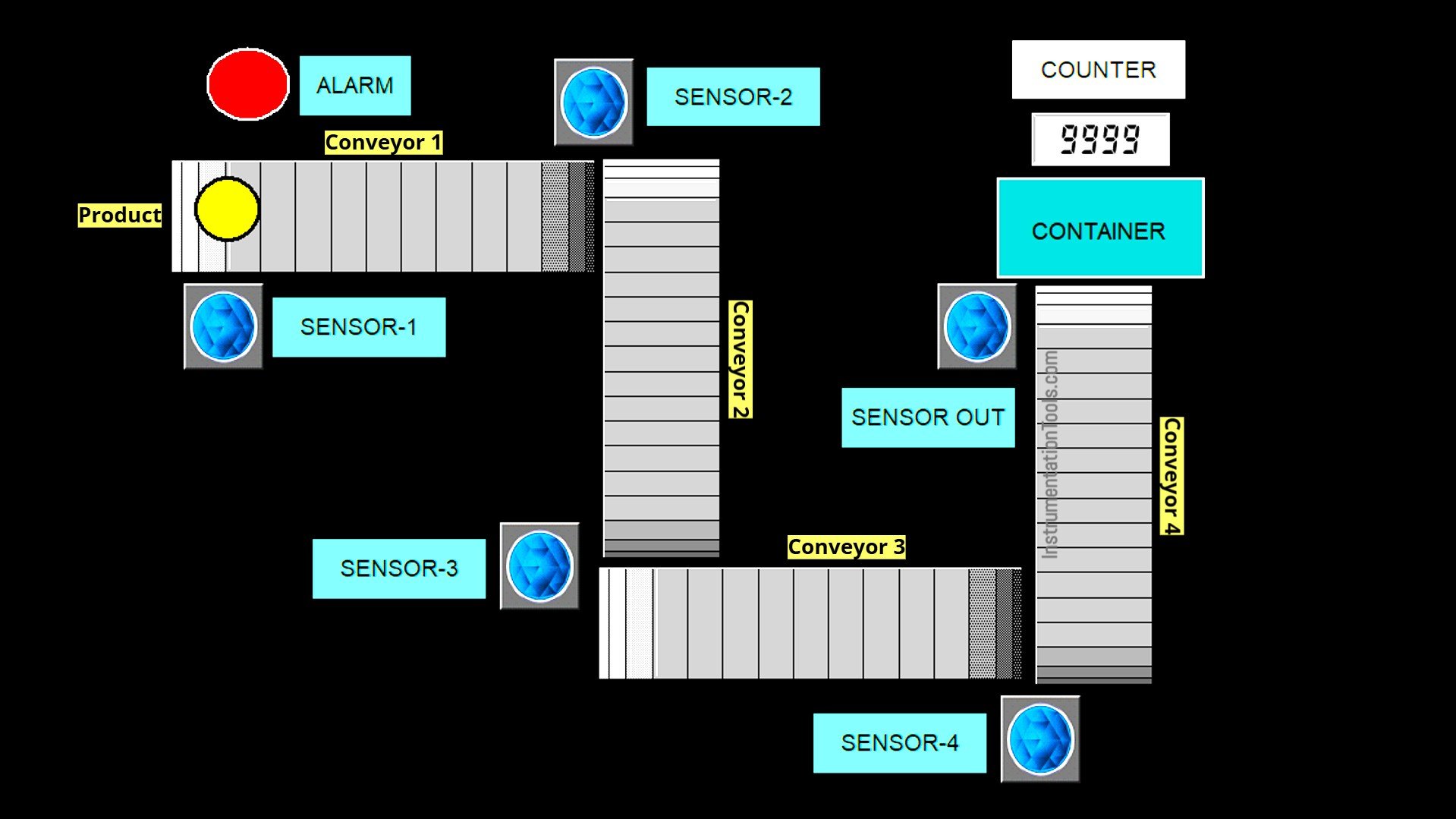
Steps of the Product Delivery Process:
- Each conveyor will operate automatically when it detects the presence of a product.
- The system consists of four conveyors: Conveyor 1, 2, 3, and 4.
- If no product is received within 10 seconds, the system will activate an alarm.
- The conveyor will stop operating once it no longer detects the presence of a product.
- All conveyors will automatically shut off after the carried product enters the collection bin.
- The system will count the number of products that have been delivered.
- When the product count reaches 10, the counter data will be automatically reset.
4 Conveyor Interlock System
IO Mapping
| S.No. | Comment | Input (I) | Output (Q) | Memory Bit | Memory Words | Timers |
|---|---|---|---|---|---|---|
| 1 | START | 0.00 | ||||
| 2 | STOP | 0.01 | ||||
| 3 | SENS_1 | 0.02 | ||||
| 4 | SENS_2 | 0.03 | ||||
| 5 | SENS_3 | 0.04 | ||||
| 6 | SENS_4 | 0.05 | ||||
| 7 | SENS_OUT | 0.06 | ||||
| 8 | PB_RESET_COUNT | 0.07 | ||||
| 9 | CONVEYOR_1 | 100.00 | ||||
| 10 | CONVEYOR_2 | 100.01 | ||||
| 11 | CONVEYOR_3 | 100.02 | ||||
| 12 | CONVEYOR_4 | 100.03 | ||||
| 13 | ALARM | 100.04 | ||||
| 14 | TIMER ALARM | T0000 | ||||
| 15 | SYSTEM_ON | W0.00 | ||||
| 16 | COUNT_PRODUCT | D0 |
Omron PLC Program
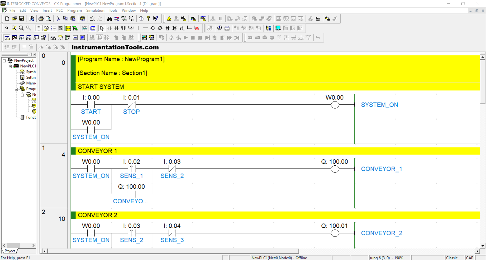
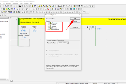
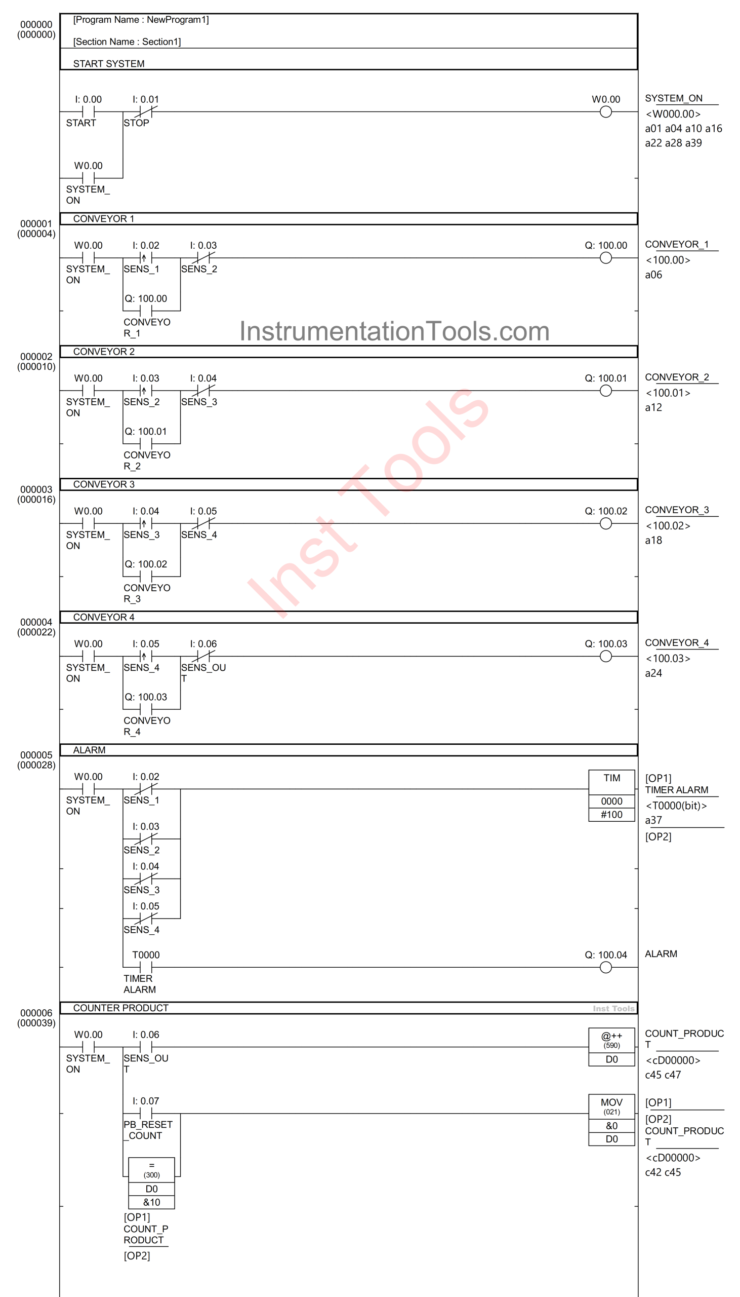
RUNG 0 (START SYSTEM)
In this Rung, if the START (0.00) button is pressed, the memory bit SYSTEM_ON (W0.00) will be in a HIGH state. Because it uses Latching, the memory bit SYSTEM_ON (W0.00) will remain in a HIGH state even though the PB_START (0.00) button has been released.
The memory bit SYSTEM_ON (W0.00) will return to a LOW state if the STOP (0.01) button is pressed.
RUNG 1 (CONVEYOR 1)
In this Rung, when the NO contact of the memory bit SYSTEM_ON (W0.00) and the SENS_1 (0.02) sensor are in a HIGH state, the CONVEYOR_1 (100.00) output will be ON. Because it uses Latching, the CONVEYOR_1 (100.00) output will remain ON even though the SENS_1 (0.02) sensor is in the LOW state.
The CONVEYOR_1 (100.00) output will return to OFF when the NC contact of the SENS_2 (0.03) sensor is in the HIGH state.
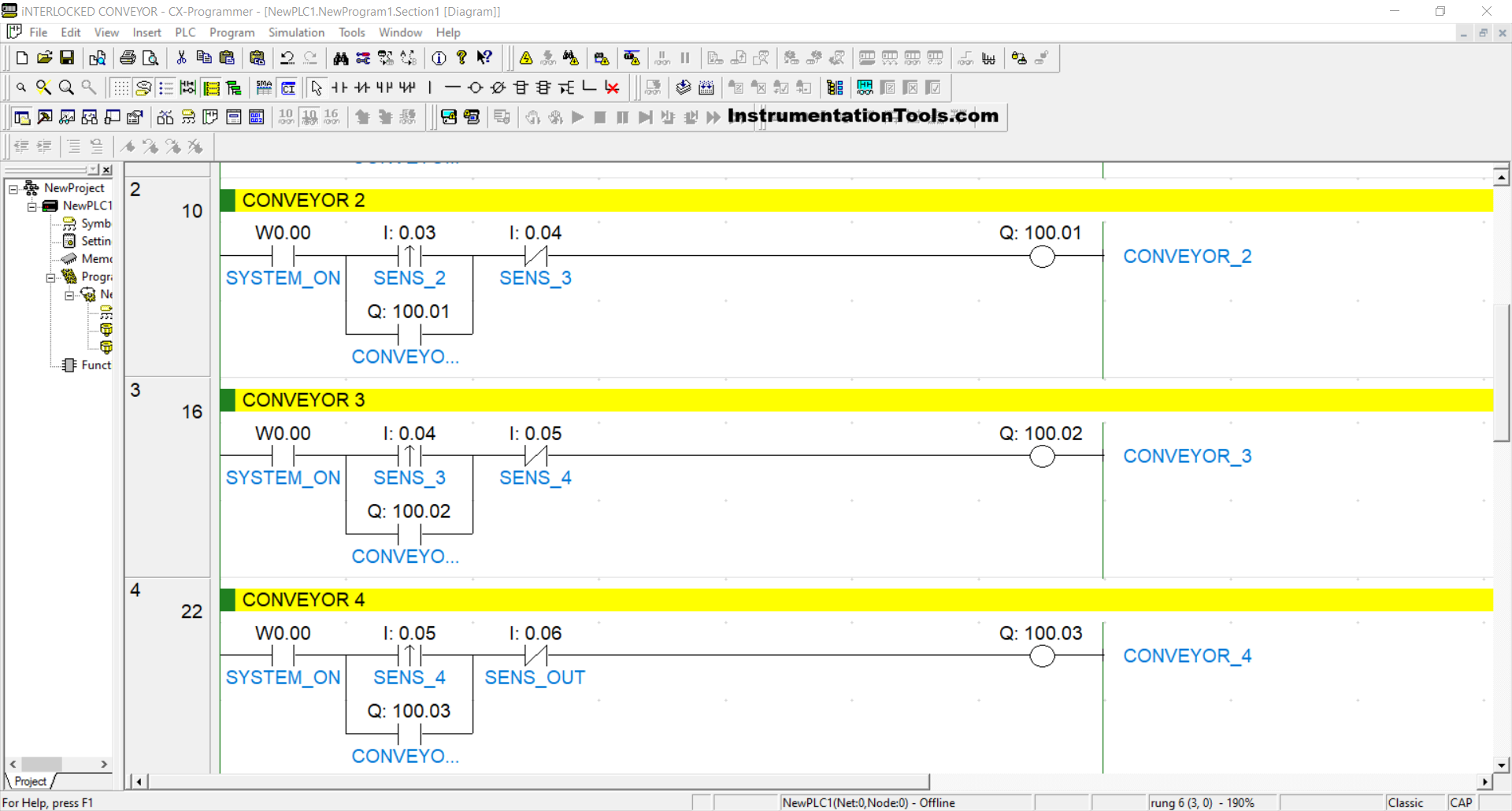
RUNG 2 (CONVEYOR 2)
In this Rung, when the NO contact of the memory bit SYSTEM_ON (W0.00) and the SENS_2 (0.03) sensor are in the HIGH state, the CONVEYOR_2 (100.01) output will be ON. Because it uses Latching, the CONVEYOR_2 (100.01) output will remain ON even though the SENS_2 (0.03) sensor is in the LOW state.
The CONVEYOR_2 (100.01) output will return to OFF when the NC contact of the SENS_3 (0.04) sensor is in the HIGH state.
RUNG 3 (CONVEYOR 3)
In this Rung, when the NO contact of the memory bit SYSTEM_ON (W0.00) and the SENS_3 (0.04) sensor are in the HIGH state, the CONVEYOR_3 (100.02) output will be ON. Because it uses Latching, the CONVEYOR_3 (100.02) output will remain ON even though the SENS_3 (0.04) sensor is in the LOW state.
The CONVEYOR_3 (100.02) output will return to OFF when the NC contact of the SENS_4 (0.05) sensor is in the HIGH state.
RUNG 4 (CONVEYOR 4)
In this Rung, when the NO contact of the memory bit SYSTEM_ON (W0.00) and the SENS_4 (0.05) sensor are in the HIGH state, the CONVEYOR_4 (100.03) output will become ON. Because it uses Latching, the CONVEYOR_4 (100.03) output will remain ON even though the SENS_4 (0.05) sensor is in the LOW state.
The CONVEYOR_4 (100.03) output will return to OFF when the NC contact of the SENS_OUT (0.06) sensor is in the HIGH state.
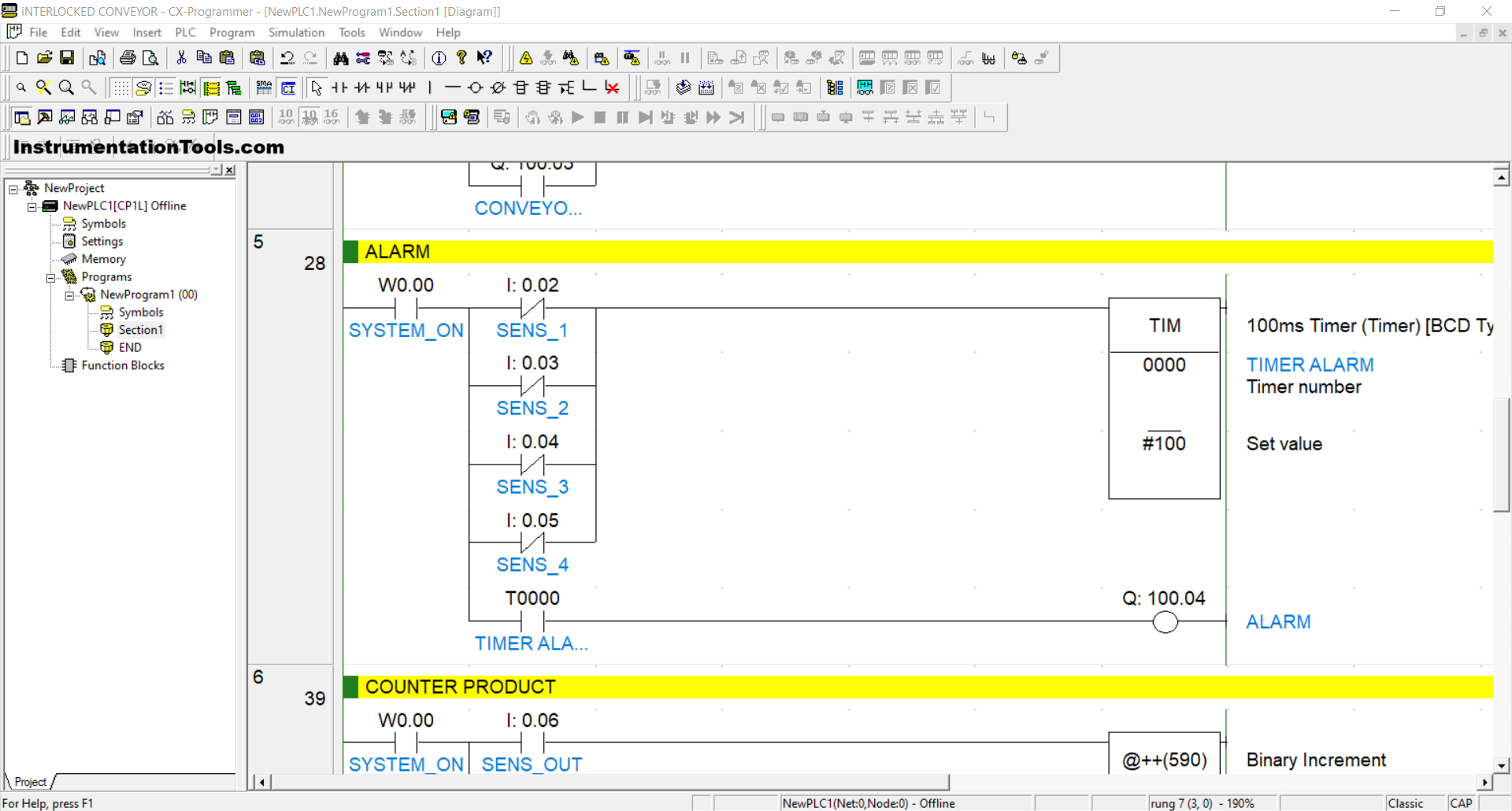
RUNG 5 (ALARM)
In this Rung, when the NO contact of the memory bit SYSTEM_ON (W0.00) is in the HIGH state, the TIMER ALARM (T0000) timer will start counting up to 10 seconds.
When the TIMER ALARM (T0000) timer has finished counting, the ALARM (100.04) output will be ON.
If any NC contact from the sensors SENS_1 (0.02), SENS_2 (0.03), SENS_3 (0.04), SENS_4 (0.05) in the HIGH state, the ALARM (100.04) output will be OFF and the timer TIMER ALARM (T0000) will be reset.
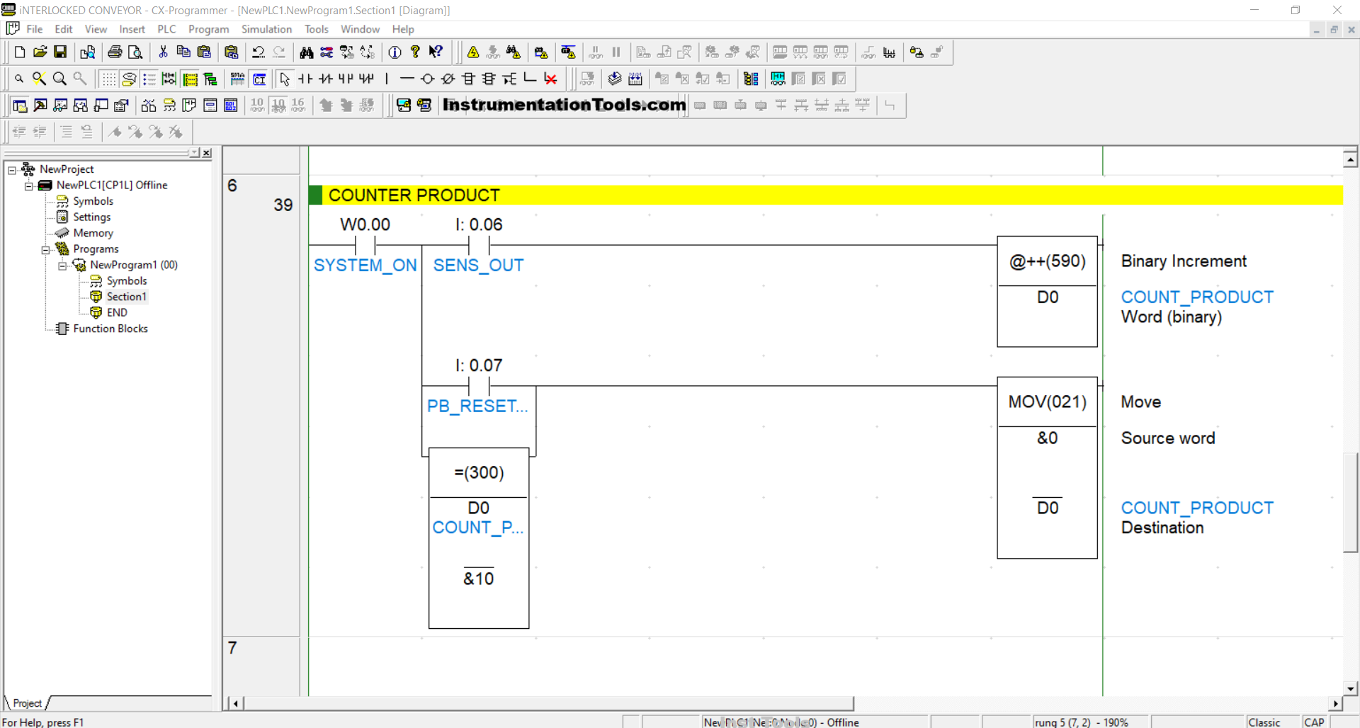
RUNG 6 (COUNTER PRODUCT)
In this Rung, when the NO contact of the memory bit SYSTEM_ON (W0.00) and the SENS_OUT(0.06) sensor are in the HIGH state, the value of the memory word COUNT_PRODUCT (D0) will increase (+1) because it uses the Binary Increment/@++ Instruction.
When the value of the memory word COUNT_PRODUCT (D0) is Equal to “10” or the PB_RESET_COUNT (0.07) button has been pressed, the value of the memory word COUNT_PRODUCT (D0) will be reset to “0”.
Read Next:
- Data Comparison Instructions in Omron PLC Example
- Detect the Speed of a Conveyor using PLC Programming
- What is Siemens TDC? – Siemens Control System
- Convert an Electrical Diagram into a PLC Program
- PLC Program to Control the Sequence of Conveyors