Learn the differences between Move, Move Bit, Move Digit, and examples of Omron PLC programs using CX-Programmer software.
Omron PLC Instructions
In industrial automation systems “Data transfer” is the most widely used function, in PLC this function is in the form of an “Instruction” that is commonly used to manipulate system parameters and move data between memory allocations.
In this article, we will discuss 3 types of data transfer instructions in CX-Programmer, namely “Move, Move Bit, Move Digit“. These three Instructions have the same function, which is to move data, but have their advantages.
Join the free Omron PLC Course – Register Now.
MOVE: MOV(021) Instruction
The Move instruction is an instruction that serves to move data from one Word Memory allocation to another Word Memory allocation. These instructions will move data when enabled.
The MOVE instruction consists of 2 parameters, namely “S: Source” as the memory allocation of the data source and “D: Destination” as the memory allocation where the moved data is accommodated.
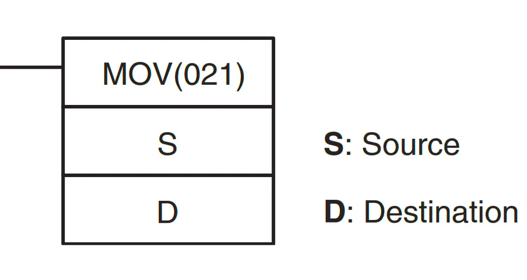
Two variations of MOV Instructions are often used in CX-Programmer. The first is “MOV(021)” When activated this instruction will move data continuously according to the number of cyclic programs.
The second variation is “@MOV(021)” This instruction will move data only once at the time of changing conditions from “OFF” to “ON” (using the concept of Differentiate UP).
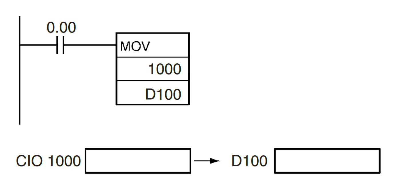
For example, in the picture above when contact (0.00) is enabled, the “MOV” instruction will move data from the address “CIO 1000” to the memory allocation “D100”.
The following is the memory allocation table for using the “MOV(021)” instruction
| Area | S | D |
| CIO Area | CIO 0 to CIO 6143 | |
| Work Area | W0 to W511 | |
| Holding Bit Area | H0 to H511 | |
| Auxiliary Bit Area | A0 to A959 | A448 to A959 |
| Timer Area | T0000 to T4095 | |
| Counter Area | C0000 to C4095 | |
| DM Area | D0 to D32767 | |
| Indirect DM addresses in binary | @ D0 to @ D32767 | |
| Indirect DM addresses in BCD | *D0 to *D32767 | |
| Constants | #0000 to #FFFF (binary) | — |
| Data Registers | DR0 to DR15 | |
| Index Registers | — | |
| Indirect addressing using Index Registers | ,IR0 to ,IR15 –2048 to +2047, IR0 to –2048 to +2047, IR15 DR0 to DR15, IR0 to IR15 ,IR0+(++) to ,IR15+(++) ,–(– –) IR0 to, –(– –) IR15 | |
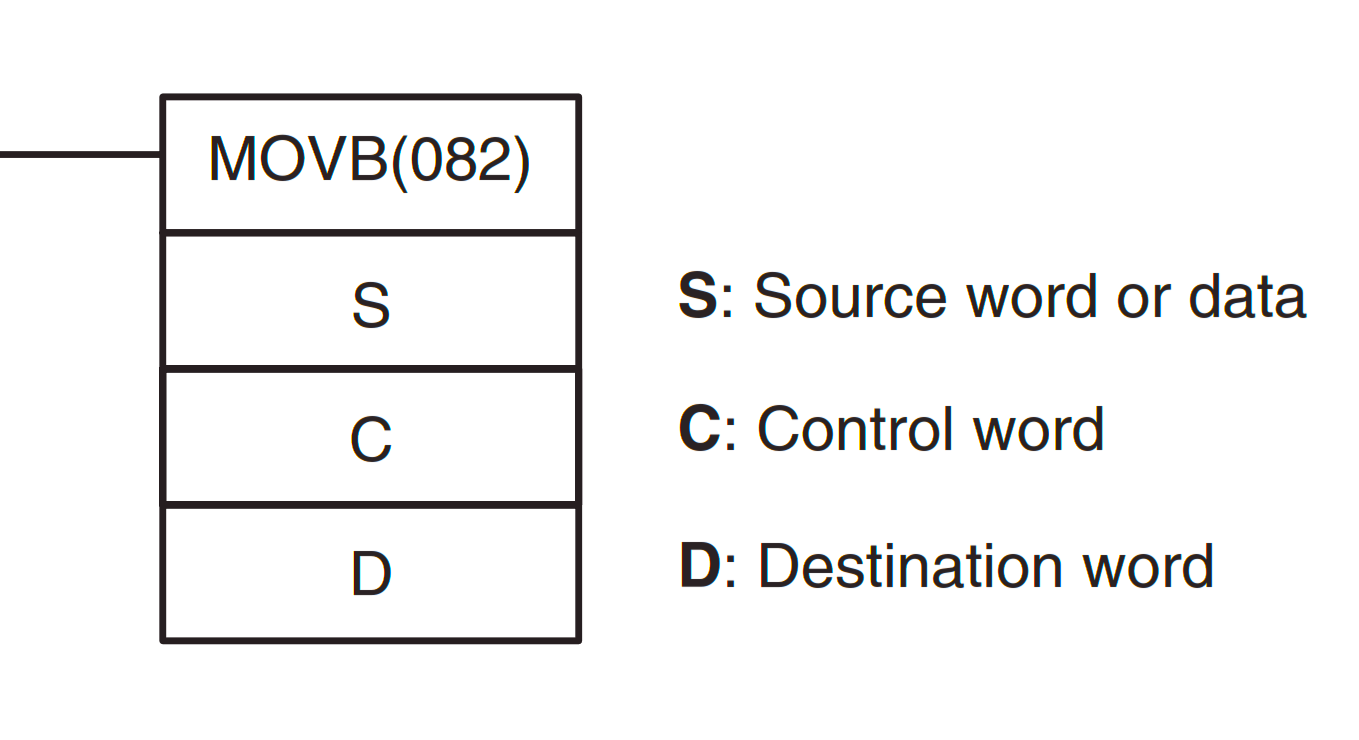
MOVE BIT: MOVB(082) Instruction
The Move Bit instruction moves the value of data from one Bit address to another Bit address. The MOVB instruction will move the data value when enabled.
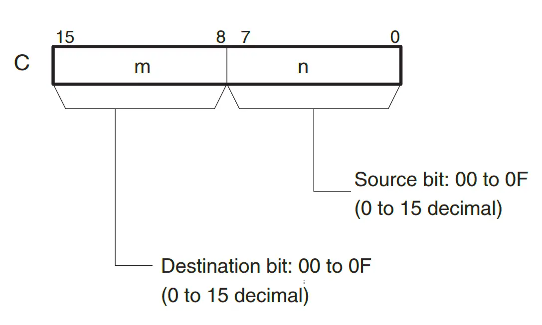
The MOVE BIT instruction has 3 parameters, namely “S: Source” as the allocation of Word Memory data source, “C: Control Word” to set the bit address retrieved data, and the destination Bit address. and “D: Destination” as the Word Memory allocation where the moved data is accommodated. Keep in mind that a data Word Memory consists of 16 bits consisting of Bits 0-15.
The image below is how Control Word works, The two rightmost digits C indicate which Bit “S” is the source bit and the “S” bit The two leftmost “C” digits indicate which Bit “D” is the destination bit.
Like the MOVE Instruction, there are 2 Variations of the MOVE BIT Instruction that are often used in CX-Programmer. The first is “MOVB(082)” When activated this instruction will move data from the Bit address continuously according to the number of cyclic programs.
The second variation is “@MOVB(082)” This instruction will move data from the Bit address only once at the time of changing the condition from “OFF” to “ON” (using the concept of Differentiate UP).
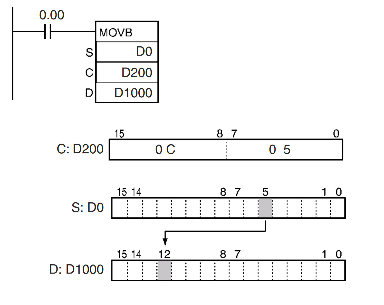
For example, in the picture above when contact (0.00) is activated it will move the data value from Bit “05” of Word Memory (D0) to the address of the destination Bit “0C(HEX) = 12 (Decimal)” Word Memory (D1000).
The following is the memory allocation table using the MOVB(082) Instruction
| Area | S | C | D |
| CIO Area | CIO 0 to CIO 6143 | ||
| Work Area | W0 to W511 | ||
| Holding Bit Area | H0 to H511 | ||
| Auxiliary Bit Area | A0 to A959 | A448 to A959 | |
| Timer Area | T0000 to T4095 | ||
| Counter Area | C0000 to C4095 | ||
| DM Area | D0 to D32767 | ||
| Indirect DM addresses in binary | @ D0 to @ D32767 | ||
| Indirect DM addresses in BCD | *D0 to *D32767 | ||
| Constants | #0000 to #FFFF (binary) | Specified values only | — |
| Data Registers | DR0 to DR15 | ||
| Index Registers | — | ||
| Indirect addressing using Index Registers | ,IR0 to ,IR15 –2048 to +2047, IR0 to –2048 to +2047, IR15 DR0 to DR15, IR0 to IR15 ,IR0+(++) to ,IR15+(++) ,–(– –) IR0 to, –(– –) IR15 | ||
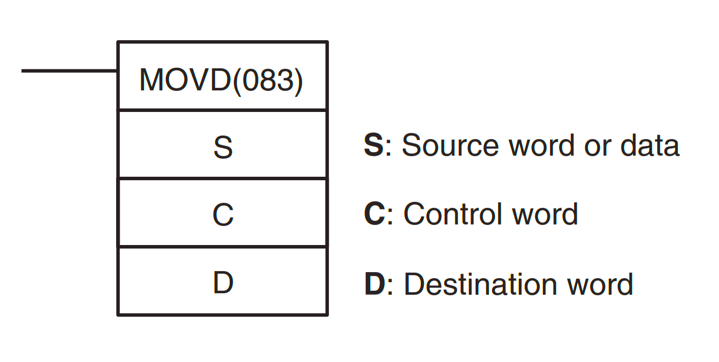
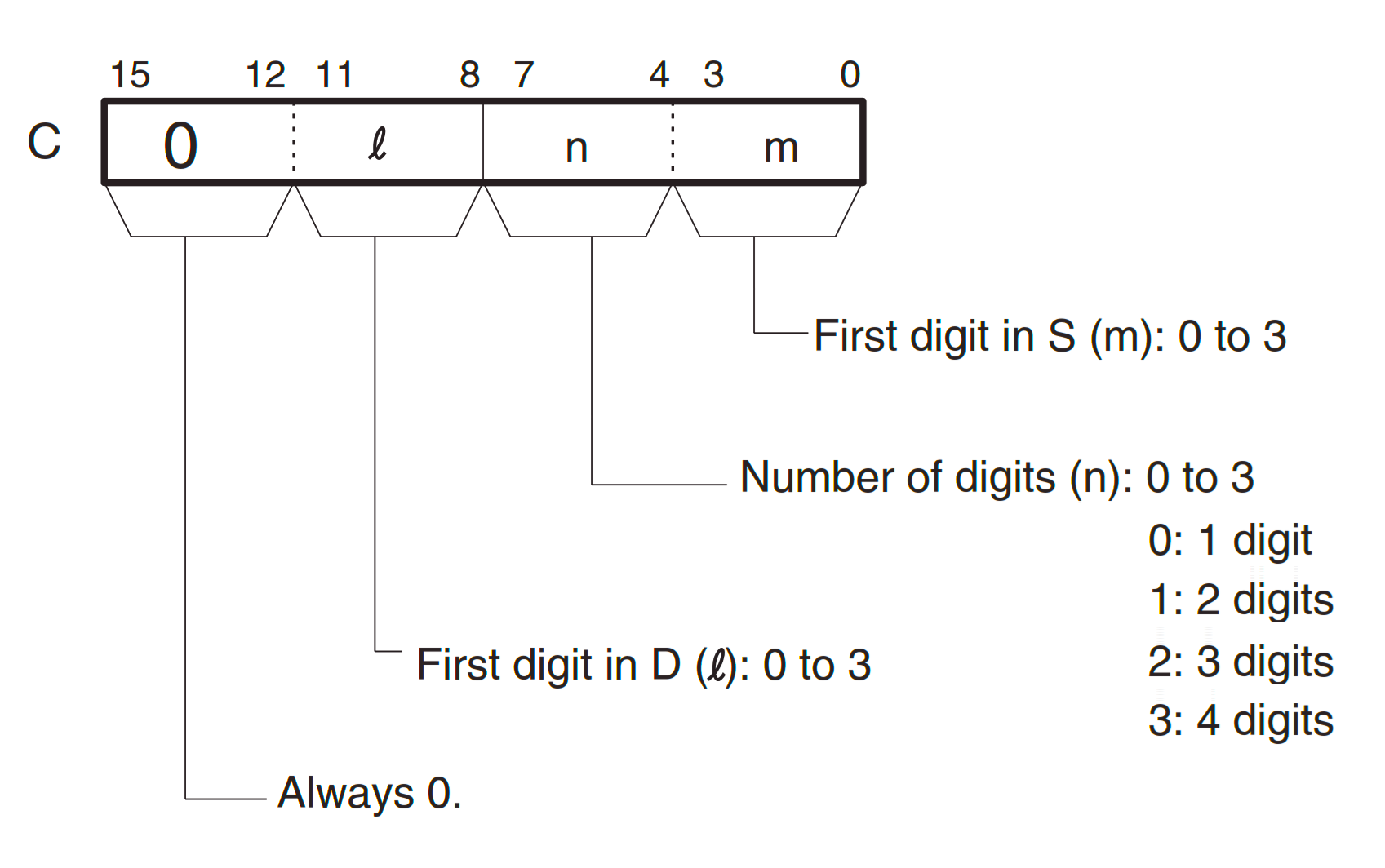
MOVE DIGIT: MOVD(083) Instruction
Move Digit Instruction moves digit data from a Word Memory address to another Word Memory address digit data.
The MOVD instruction has 3 parameters, namely “S: Source” as the Word Memory allocation of the Digit data source to be retrieved, “C: Control Word” to set the Digit address taken data, and the destination Digit address. and “D: Destination” as the Word Memory allocation where the moved Digit data is accommodated.
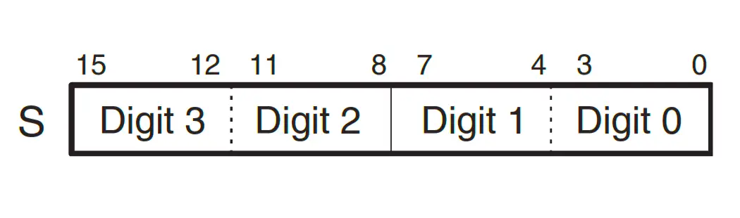
1 digit data = 4 Bits, so in 1 Word Memory address contains 4 Digits data. With bits 0-3 = digits 0, bits 4-7 = digits 1, bits 8-11 = digits 2, bits 12-15 = digits 3.
The way the MOVD Control Word works is The first three digits of C indicate the source digit (m), the number of digits transferred (n), and the first destination digit (l).
In this Instruction, the Order and number of Digits to be taken can be determined, and the Destination Digit Order of data can also be determined.
Like the Move & Move Bit Instruction, there are 2 variations of the MOVE DIGIT Instruction that are often used in CX-Programmers, the first is “MOVD(083)” When activated this instruction will move data from a Digit address continuously according to the number of cyclic programs.
The second variation is “@MOVD(083)”. This instruction will move data from a Digit address only once when the condition changes from “OFF” to “ON” (using the concept of Differentiate UP).
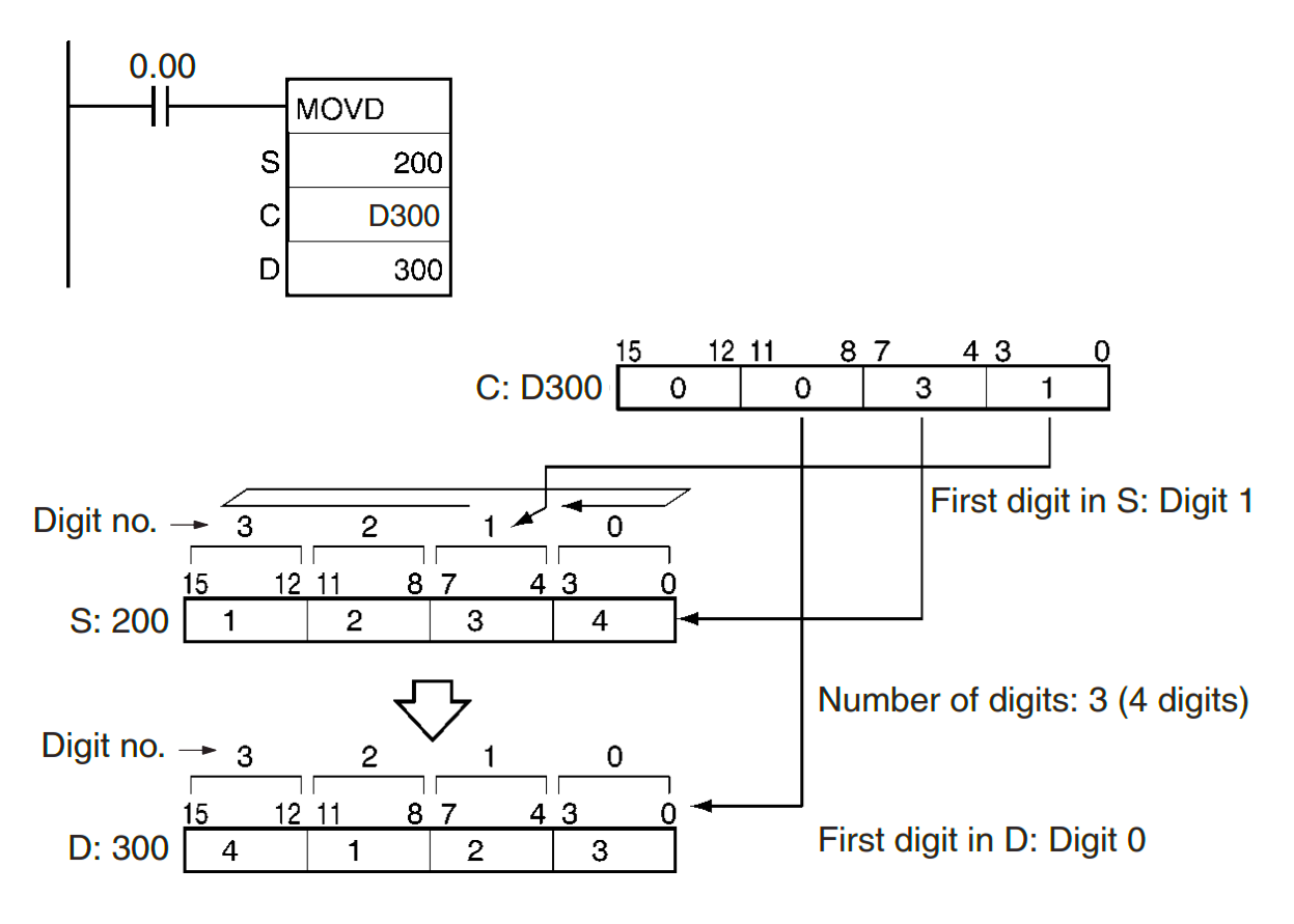
For example, in the figure above When a contact (0.00) “ON” four digits of data are moved from CIO “200” to CIO “300”.
The move begins at Digit 1 of the CIO “200” and is accommodated at Digit “0” of the CIO address “300”, corresponding to the Control Word value “0031”.
The following is the memory allocation table using the MOVD(083) Instruction.
| Area | S | C | D |
| CIO Area | CIO 0 to CIO 6143 | ||
| Work Area | W0 to W511 | ||
| Holding Bit Area | H0 to H511 | ||
| Auxiliary Bit Area | A0 to A959 | A448 to A959 | |
| Timer Area | T0000 to T4095 | ||
| Counter Area | C0000 to C4095 | ||
| DM Area | D0 to D32767 | ||
| Indirect DM addresses in binary | @ D0 to @ D32767 | ||
| Indirect DM addresses in BCD | *D0 to *D32767 | ||
| Constants | #0000 to #FFFF (binary) | Specified values only | — |
| Data Registers | DR0 to DR15 | ||
| Index Registers | — | ||
| Indirect addressing using Index Registers | ,IR0 to ,IR15 –2048 to +2047, IR0 to –2048 to +2047, IR15 DR0 to DR15, IR0 to IR15 ,IR0+(++) to ,IR15+(++) ,–(– –) IR0 to, –(– –) IR15 | ||
Sample Omron Programming
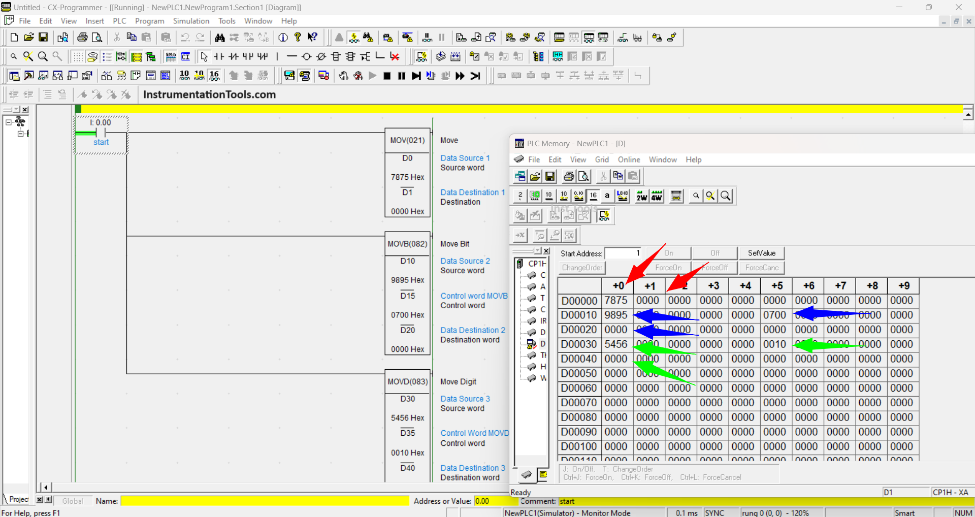
In this PLC Program, when the START contact (0.00) is activated, the MOV, MOVB, and MOVD Instructions will move data from the source address to the destination address.
The Source and Control Word values of each Instruction have been applied, but the data has not been moved because the START contact (0.00) is still not enabled.
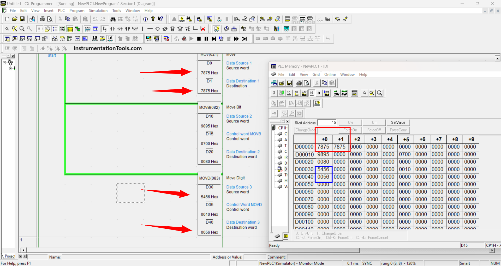
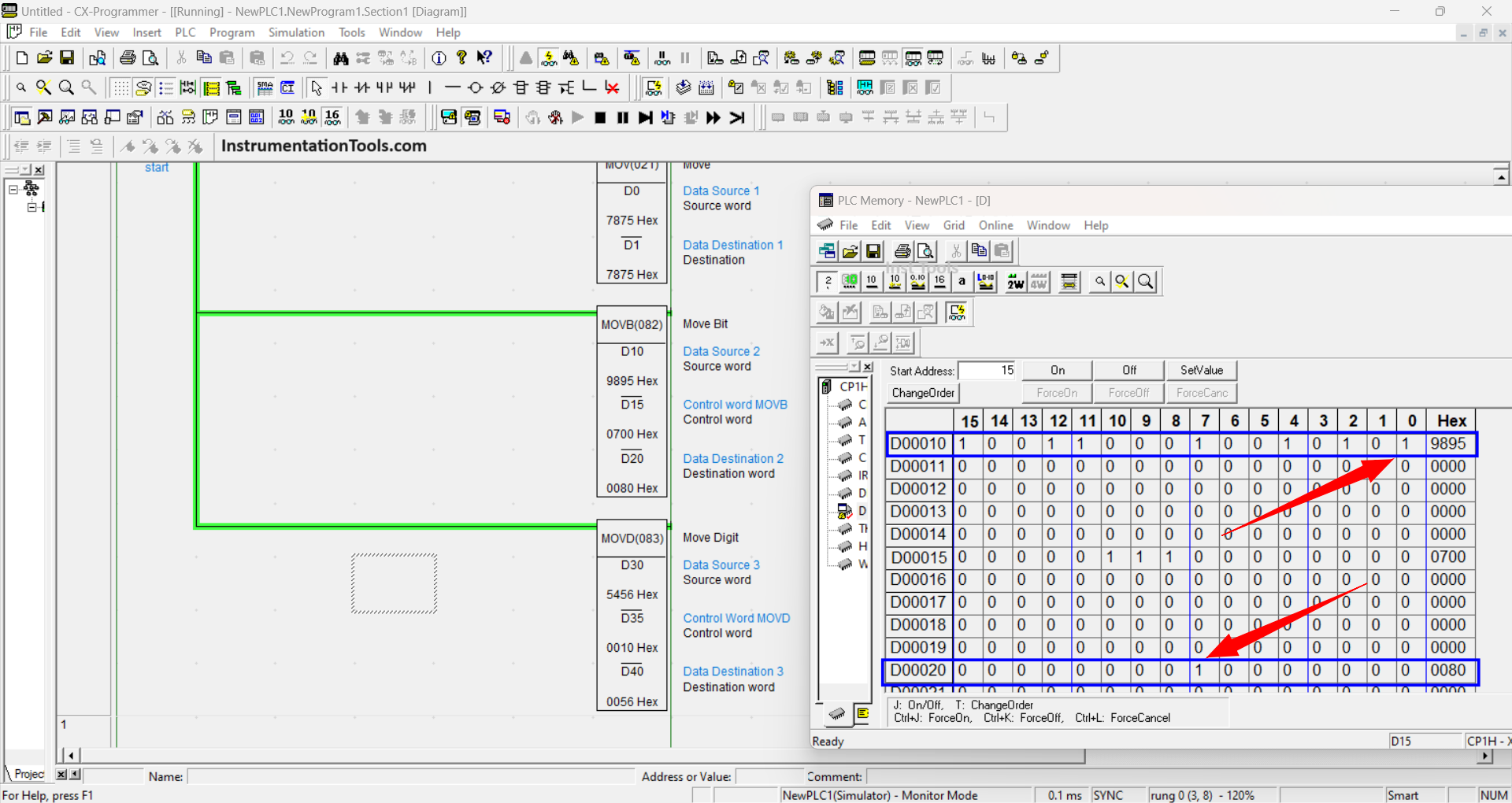
The picture below shows when the start contact (0.00) has been activated, the data from the MOV Instruction has been moved from the source address (D0=7875) to the Destination address (D1=7875).
Data from the MOVD Instruction has also been moved from the source (D30=5456) to the address (D40=0056), the data moved by two digits (0056) because the Control Word parameter set is (0010).
The picture below is the result of the transfer from the MOVB Instruction. Because the MOVB Instruction moves Bit data, the PLC memory display must be set to Binary units in the Pop-up window.
It can be seen that the D10 address at Bit-0 at “1” has been moved to the address D20 at Bit-7 at “1”, according to the Control Word parameter “0010”.
If you liked this article, please subscribe to our YouTube Channel for PLC and SCADA video tutorials.
You can also follow us on Facebook and Twitter to receive daily updates.
Read Next:
- From Boolean Algebra to PLC Ladder Logic
- Manufacturing Line Assembly PLC Program
- Electrical Drives Speed Control Application
- PLC Ladder Logic Motor with Toggle Switch
- Electrical Ladder Diagram Control using Timers


![Multi-Tank Liquid Level Control System with Fill Priority [PLC]](https://instrumentationtools.com/wp-content/uploads/2025/07/Multi-Tank-Liquid-Level-Control-System-with-Fill-Priority-PLC-420x280.jpg)