Temperature can be measured via a diverse array of sensors. All of them infer temperature by sensing some change in a physical characteristic. There are four basic types of temperature measuring devices, each of which uses a different principle:
- Mechanical (liquid-in-glass thermometers, bimetallic strips, bulb & capillary, pressure type etc.)
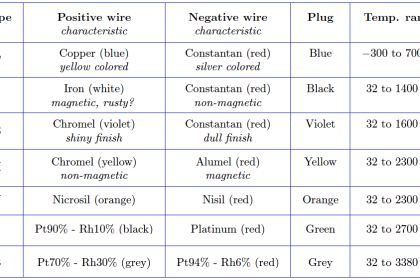
- Thermojunctive (thermocouples)
- Thermoresistive (RTDs and thermistors)
- Radiative (infrared and optical pyrometers)
Mechanical Temperature Measuring devices
Principle of Operation
A change in temperature causes some kind of mechanical motion, typically due to the fact that most materials expand with a rise in temperature. Mechanical thermometers can be constructed which use liquids, solids, or even gases as the temperature-sensitive material.
The mechanical motion is read on a physical scale to infer the temperature. The examples include:
- Liquid-in-glass thermometer
The most common and well-known thermometer is the liquid-in-glass thermometer.
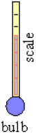
As the temperature rises, the liquid expands, moving up the tube. The scale is calibrated to read temperature directly. Usually, mercury or some kind of alcohol is used for the liquid.
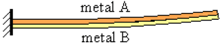
- Bimetallic strip thermometer
Two dissimilar metals are bonded together into what is called a bimetallic strip as figured below.
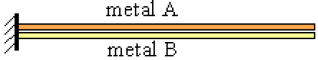
Suppose metal A has a smaller coefficient of thermal expansion than does metal B. As temperature increases, metal B expands more than does metal A, causing the bimetallic strip to curl upwards as sketched.
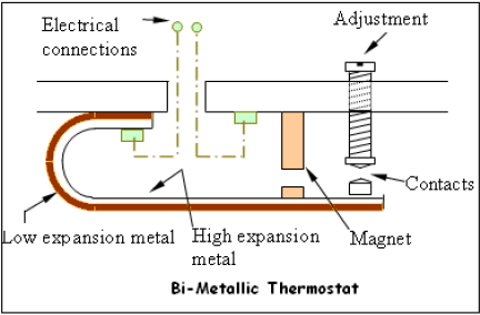
One common application of bimetallic strips is in air-conditioning thermostats, where a bimetallic strip is used as the arm of a switch between electrical contacts. As the room temperature changes, the bimetallic strip bends as discussed above. When the bimetalic strip bends far enough, it makes contact with electrical leads which turn the heat or air conditioning on or off.
Another common application is for use as oven thermometers or wood burner thermometers. These thermometers consist of a bimetallic strip wound up in a spiral, attached to a dial which is calibrated into a temperature scale.
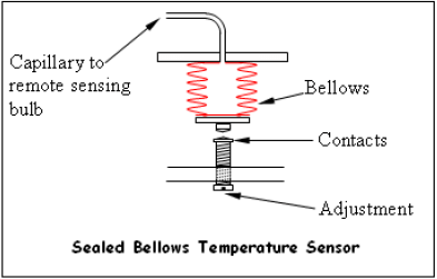
- Sealed Bellows
The sealed bellows type is filled with a gas, vapor or liquid, which responds to change in temperature by variation in volume and pressure causing expansion or contraction.
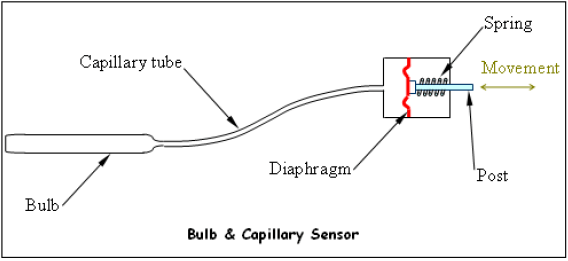
- Bulb and Capillary Sensor
Bulb and capillary elements are used where temperatures are to be measured in ducts, pipes, tanks or similar locations remote from the controller.
The bulb is filled with liquid, gas or refrigerant depending on the temperature range required. Expansion of the fluid in the heated bulb exerts a pressure which is transmitted by the capillary to the diaphragm and there translated into movement.
- Pressure thermometer
A pressure thermometer, while still considered mechanical, operates by the expansion of a gas instead of a liquid or solid. (Note: There are also pressure thermometers which use a liquid instead of a gas.)
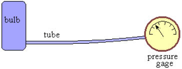
Suppose the gas inside the bulb and tube can be considered an ideal gas.
The ideal gas law is PV = m R T
Where
- P is the pressure,
- V is the volume of the gas,
- m is the mass of the gas,
- R is the gas constant for the specific gas (not the universal gas constant), and
- T is the absolute temperature of the gas.
The bulb and tube are of constant volume, so V is a constant. Also, the mass, m, of gas in the sealed bulb and tube must be constant. Hence, the above equation reduces to P = kT, where k is constant.
A pressure thermometer therefore measures temperature indirectly by measuring pressure. The gage is a pressure gage, but is typically calibrated in units of temperature instead.
A common application of this type of thermometer is measurement of outside temperature from the inside of a building. The bulb is placed outside, with the tube running through the wall into the inside. The gauge is on the inside. As T increases outside, the bulb temperature causes a corresponding increase in pressure, which is read as a temperature increase on the gauge.
Also Read: Basics of Thermocouples & RTD