In this article, we shall learn about general specifications for the design and installation of level instruments, transmitters, and switches.
Level Instruments Specifications
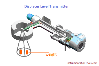
External displacer type instruments with side-side connections and rotatable head shall normally be used for level measurement up to 1219 mm. Side-bottom connections are preferred where RTJ (Ring Joint Flange) flanges are required. Internal displacer type of level transmitters shall be avoided unless application necessitates its use. Stilling well shall be provided for internal displacer.
Conventional Electronic transmitters shall be two-wire, 24 VDC, 4-20 mA output with HART Protocol. Specifications for DP type level transmitters shall be as elaborated in Standard Specification for Pressure/DP Instruments.
A separate Hand-held communicator with necessary software for communication loaded shall be provided along with displacer level transmitters.
All displacer type level transmitters shall be of torque tube type with torque tube material of Inconel, as a minimum. Accuracy of displacer type level transmitters shall be +/- 0.5%.
The standard materials shall be as a minimum: –
Displacer: 316 SS
Torque tube: Inconel
Chamber: Carbon Steel
Finned torque tube extensions shall be provided as necessary for high or low-temperature service conditions.
In general, displacer type instruments shall be used with displacer lengths of 356 mm, 813 mm, and 1219 mm. For interface level measurement, displacer type instruments shall only be used.
Differential pressure transmitters shall be used for level measurement above 1219 mm for services requiring purge or where liquid might boil in the external portion.
Differential pressure transmitters for use on corrosive or fouling service shall generally be diaphragm wafer with filled capillary type. Flush or extended diaphragm type differential pressure transmitters shall be considered for special applications only. Diaphragm material shall normally be stainless steel or any other special alloy. Transmitters for closed vessels shall have a correction for suppression or elevation.
Also Read: Transmitter Detailed Specifications
Dip Tube type level transmitters may be used on corrosive, congealing, slurry services where suitable diaphragm seal type transmitter is difficult to obtain or where accuracy is not of prime importance.
In general, level switches shall be avoided. However, when specified, level switches shall generally, be external ball float type with flanged head. External displacer type level switches can be considered for lighter fluids where specific gravity is less than 0.5. Internal float/displacer type level switches shall only be used if external ball float/displacer type is not possible, like in viscous services and in underground tanks/vessels.
The low-level switch shall be mounted directly on the column when the setpoint is not less than 630mm. When level gauge and level switch are on the same standpipe, the minimum allowable low-level setpoint shall be 480mm on the column.
The switch shall be sealed micro type with contact rating suitable for the specific application. Level switches with reed switch shall not be used.
The level switch shall be furnished with SPDT contacts with adjustable differential unless otherwise specified.
Tuning fork, capacitance, displacer, or paddle-type level switch may be used wherever application calls for such a device.
Mechanical float type gauge shall be used for atmosphere tanks and vessels where level measurement accuracy requirement is of the order of ± 2 mm. The liquid seal chamber shall be used where tank contents are toxic or tank is blanketed. The float shall be of 316 stainless steel as a minimum. Cages shall be carbon steel as standard unless service conditions demand a higher specification.
Servo controlled gauges shall be used for level measurement of pressurized tanks/vessels/spheres requiring remote signal transmission and better level measurement accuracies. The level/data transmission signal shall be digital-only. Servo type instruments shall have 6″ process connection with 12″ dia still well. The accessories for servo-controlled level gauge shall include calibration chamber, operator keys for moving the displacer, and isolation ball valves for pressurized tanks.
The tank side indicator for both types of gauges shall have hoisting facilities. All tank level gauges shall have side-mounted indicator – counter type for mechanical float type and solid-state digital for servo-controlled level gauge.
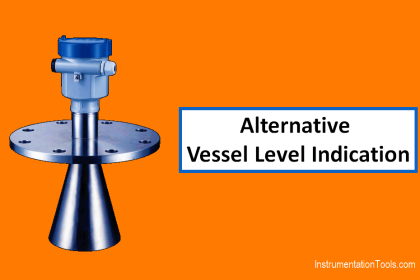
RADAR type tank gauges shall be used for storage tanks handling viscous fluids, pressurized tanks, or as specified in the job specifications.
The wetted material like float, displacer, tape, wire, etc. shall be minimum 316 SS.
Standpipe shall be used for clean, non-viscous, and non-crystallizing services if more than 4 nozzles are required for level instruments, e.g. one displacer instrument and one level gauge can be mounted directly on the equipment.
The maximum number of nozzles on the standpipe shall be limited to: –
- 8 nos. with no displacer type level instrument on it
- 6 nos. with displacer type level instrument on it.
The size of standpipe shall be 2² NB minimum and valved at the instrument connections.
Trip level switches should be directly mounted on vessel/column and not on standpipe. The connection of standpipe from the bottom of the vessel should be avoided.
On horizontal vessels with the boot, separate standpipe shall be used for boot interface level measurement in addition to standpipe used for the horizontal vessels.
Interest to add any further points? Share with us through below comments section.
Author: Kalpit Patel
Read Next:
- Types of Level Gauges
- Level Measurement Accuracy
- Tank Gauging Methods
- Level Gauge Design
- Level Transmitters Design