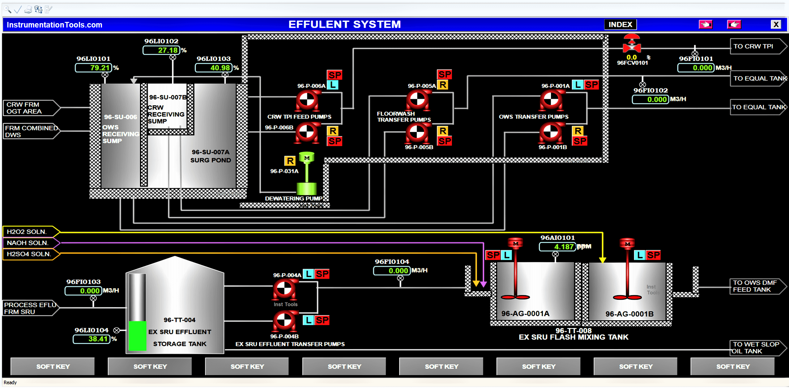
In this article, we will learn about the SCADA and HMI systems in industrial automation, also the differences and comparisons.
The graphical interface is a must in industrial automation to view the graphics and control actions happening inside a PLC or other controller. The two commonly used graphical interfaces are HMI and SCADA.
HMI stands for Human Machine Interface, and SCADA stands for Supervisory Control and Data Acquisition. Both have the same task of graphical display, but stand out from each other in some differences. In this post, we will see the difference between HMI and SCADA.
Let us first understand the flow of system control. Consider we are using a button, motor, PLC, and HMI / SCADA. A button is a digital input for PLC and a motor is a digital output for PLC.
In the HMI / SCADA screen, you are showing the status of the motor. It is communicating with PLC and shows the status through it.
On pressing the button, the logic written in PLC turns on the motor. So, the motor status will turn from red to green on the display screen.
Basically, HMI or SCADA is just like the regular monitor that we use. It has no brain; it just shows all the processes happening inside the CPU.

In the same way, it needs to communicate with PLC for showing and data.
To control data, if we consider the previous example; instead of a hardwired push button, you can show a button on the display and make it editable for the user. The user will press the button on the display and can eventually start the motor.
Free SCADA Training Courses:
Let us see the differences between both of them. First of all, SCADA is software that needs to be installed in a PC for working; whereas HMI is an individual device itself which just needs to be powered up.
As it is an individual device, it needs a separate SMPS wherever it is installed; whereas a PC can normally be powered up as we use it in daily life.
Suppose there are 10 processes in a plant. In that case, 10 HMI’s will be required for the individual processes. Obviously, a single HMI can also control all the 10 processes.
But, HMI has some limitations in communication. It will not completely slow down the communication of 10 PLC’s in a big way and show data in a lagging way; but yes, as more controllers are added to the single HMI, a bit of communication lag will happen in the HMI and the data will be shown a little slower in it.
For this purpose, SCADA is used. SCADA is purposely designed for such cases where you have to show all the processes of the plant on a single screen. Communication is way faster in it and it will show all the data smoothly.
HMI is cheaper than SCADA. If you have only two processes, it makes sense to connect a single HMI for 2 PLC’s; instead of using a SCADA.
HMI and SCADA are even both used in tandem in many cases. In our previous example of 10 processes, it makes sense to connect 10 HMI’s for individual stations so that the local operator can understand them easily. And, connect a SCADA in the central control room for an engineer to monitor the whole plant.
In terms of features, SCADA is a bit higher in functions like server-client, audit trail, reporting, web server, trends, database, etc.
Mostly, HMI has all this too apart from the server-client function. But, even in the available functions, it has some limitations as compared to that available in SCADA. It is because SCADA is designed for handling large-scale processes and this requires it to be at a higher level every time for properly controlling the plant.
In this way, we understood some general differences between HMI and SCADA.
If you liked this article, then please subscribe to our YouTube Channel for Instrumentation, Electrical, PLC, and SCADA video tutorials.
You can also follow us on Facebook and Twitter to receive daily updates.
Read Next:
Learn an example PLC program to control a pump based on level sensors using ladder…
In the PLC timer application for security camera recording, when motion is detected then camera…
In this example, we will learn batch mixing with PLC ladder logic program using timer…
This PLC example on manufacturing line assembly is an intermediate-level PLC program prepared for the…
In this article, you will learn the PLC programming example with pushbutton and motor control…
This article teaches how to convert Boolean logic to PLC programming ladder logic with the…
View Comments
Hi,
How we calculate optical fibre cable losses.