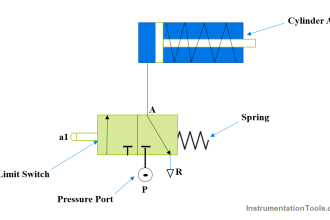
This article discusses the implementation of the Latching and Interlock concepts in a PLC program for controlling a pump with 3 different buttons using PLC with XG-5000 Software. In this system, the pump can only be activated by one button at a time. Each button is interlocked with the others, ensuring that the buttons cannot operate simultaneously.
Program Objective
Step-by-Step System:
- The system will be in Standby mode when the START button is pressed.
- There are 3 buttons to start running the Pump: RUN-1, RUN-2, and RUN-3.
- Each button will interlock with the others and has a Latching function, so even if the button (RUN-1, RUN-2, or RUN-3) is released, the pump will remain ON.
- The RUN-1, RUN-2, and RUN-3 buttons can only operate alternately.
- The pump will only turn OFF if the STOP button is pressed.
Latching and Interlocking Pump Control
IO Mapping
| S.No. | Comment | Input (I) | Output (Q) | Memory Bits |
|---|---|---|---|---|
| 1 | START | P0000 | ||
| 2 | STOP | P0001 | ||
| 3 | RUN_1 | P0002 | ||
| 4 | RUN_2 | P0003 | ||
| 5 | RUN_3 | P0004 | ||
| 6 | PUMP | P0040 | ||
| 7 | LAMP_1 | P0041 | ||
| 8 | LAMP_2 | P0042 | ||
| 9 | LAMP_3 | P0043 | ||
| 10 | SYSTEM_ON | M0000 |
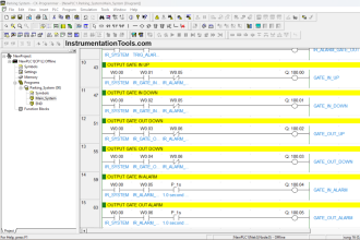
PLC Logic
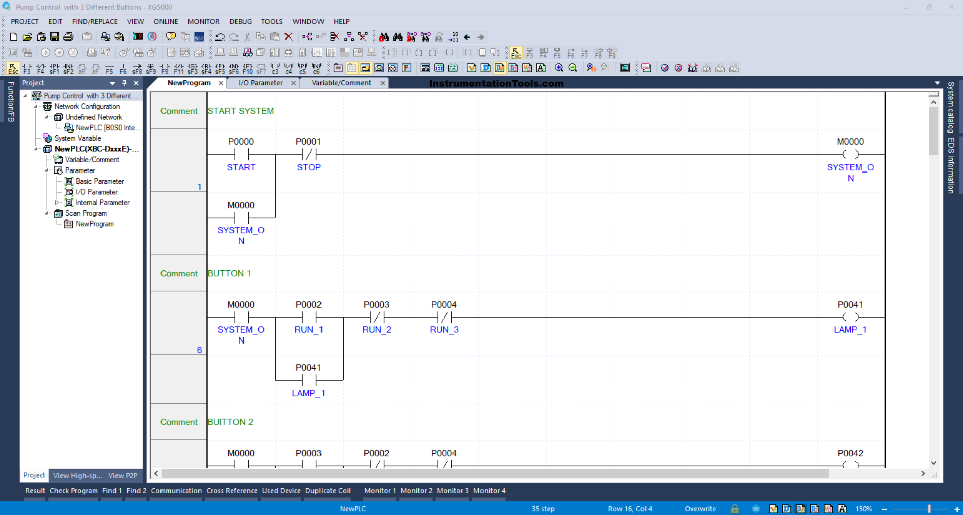
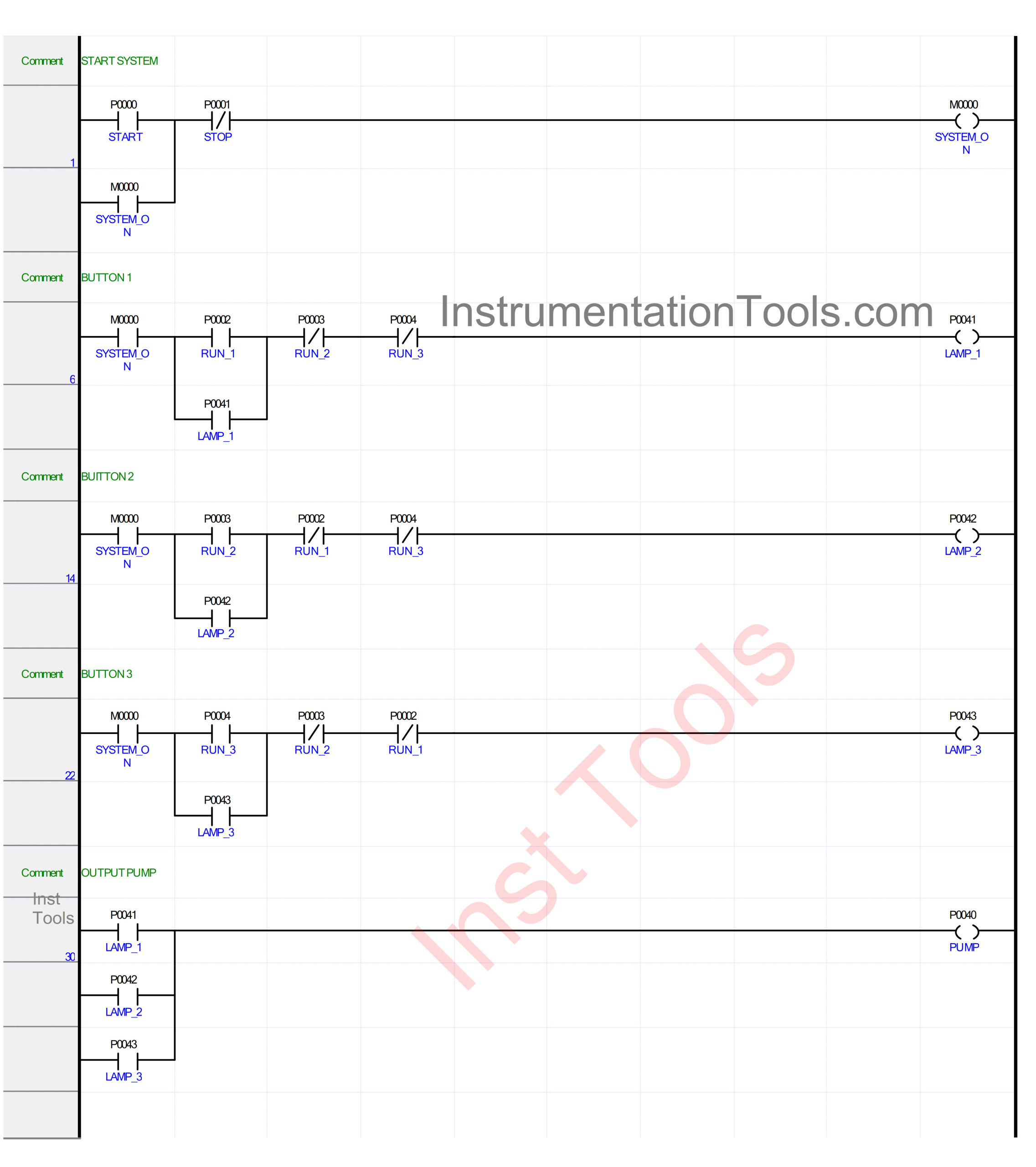
RUNG 1 (START SYSTEM)
In this rung, when the START (P0000) button is pressed, the memory bit SYSTEM_ON (M0000) will be in the HIGH state. Because latching is used, the memory bit SYSTEM_ON (M0000) remains in the HIGH state even though the START (P0000) button is released.
If the STOP (P0001) button is pressed, the memory bit SYSTEM_ON (M0000) will be in the LOW state.
RUNG 6 (BUTTON 1)
When the NO contact of the memory bit SYSTEM_ON (M0000) is in a HIGH state and the RUN_1 (P0002) button is pressed, the output LAMP_1 (P0041) will turn ON.
Even though the RUN_1 (P0002) button is released, the output LAMP_1 (P0041) will remain ON due to the use of latching.
The output LAMP_1 (P0041) will turn OFF when the RUN_2 (P0003) or the RUN_3 (P0004) buttons are pressed.
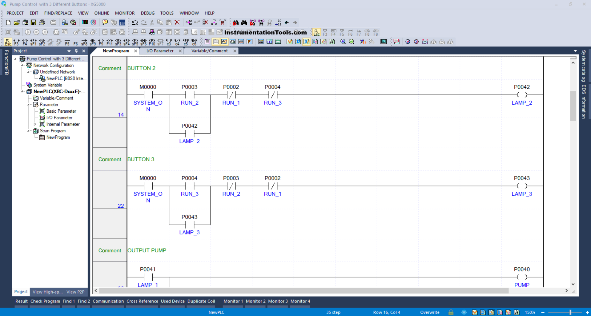
RUNG 14 (BUTTON 2)
When the NO contact of the memory bit SYSTEM_ON (M0000) is in a HIGH state and the RUN_2 (P0003) button is pressed, the output LAMP_2 (P0042) changes to an ON state.
Even if the RUN_2 (P0003) button is released, the output LAMP_2 (P0042) will remain ON because it uses latching.
When the RUN_1 (P0002) or the RUN_3 (P0004) buttons are pressed, the output LAMP_2 (P0042) will turn OFF.
RUNG 22 (BUTTON 3)
When the NO contact of the memory bit SYSTEM_ON (M0000) is in a HIGH state and the RUN_3 (P0004) button is pressed, the output LAMP_3 (P0043) changes to an ON state.
The output LAMP_3 (P0043) will remain ON even if the RUN_3 (P0004) button is released because it uses latching.
When the RUN_1 (P0002) or the RUN_2 (P0003) buttons are pressed, the output LAMP_3 (P0043) will turn OFF.
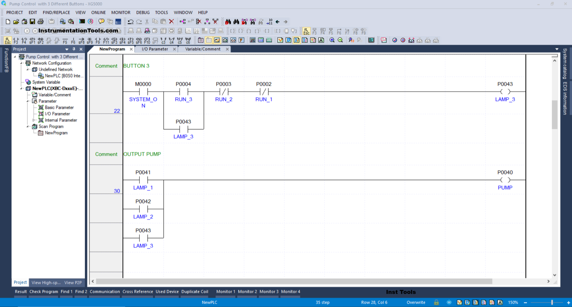
RUNG 30 (OUTPUT PUMP)
In this rung, if any one of the NO contacts from LAMP_1 (P0041), LAMP_2 (P0042), and LAMP_3 (P0043) is in a HIGH state, then the PUMP output (P0040) will turn ON.
Read Next:
- Solenoid Operated Valves and Latching Valves
- Getting to Know the LED Indications on the GE Make PLC
- Most Asked Questions on PLC SCADA System with Answers
- Difference between Machine Expert Basic and Machine Expert
- Hardwired I/O and Serial I/O in PLC System Explained