Learn how to create logic using Wonderware InTouch SCADA software using the scripting language.
InTouch Scada Scripting
There are six types of logic gates. We can create a voting system using them and also, we can create PLC programming logic using a combination of them.
Here I will create a script to turn ON lamp by using all logic gates. To do that so, open InTouch application.
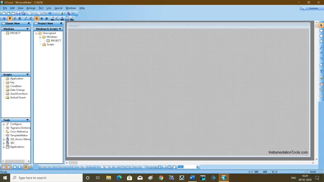
Step 1:
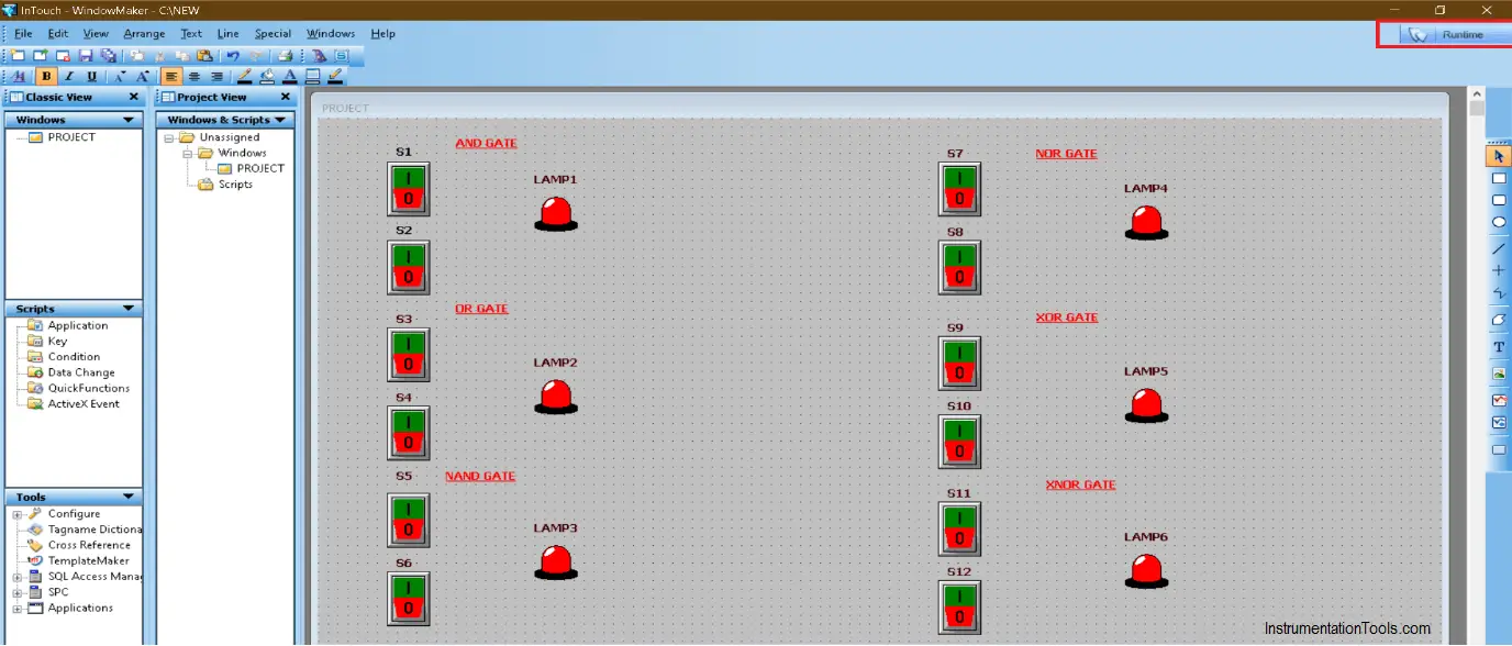
Create a new project and enter an animation environment as shown in the below window.
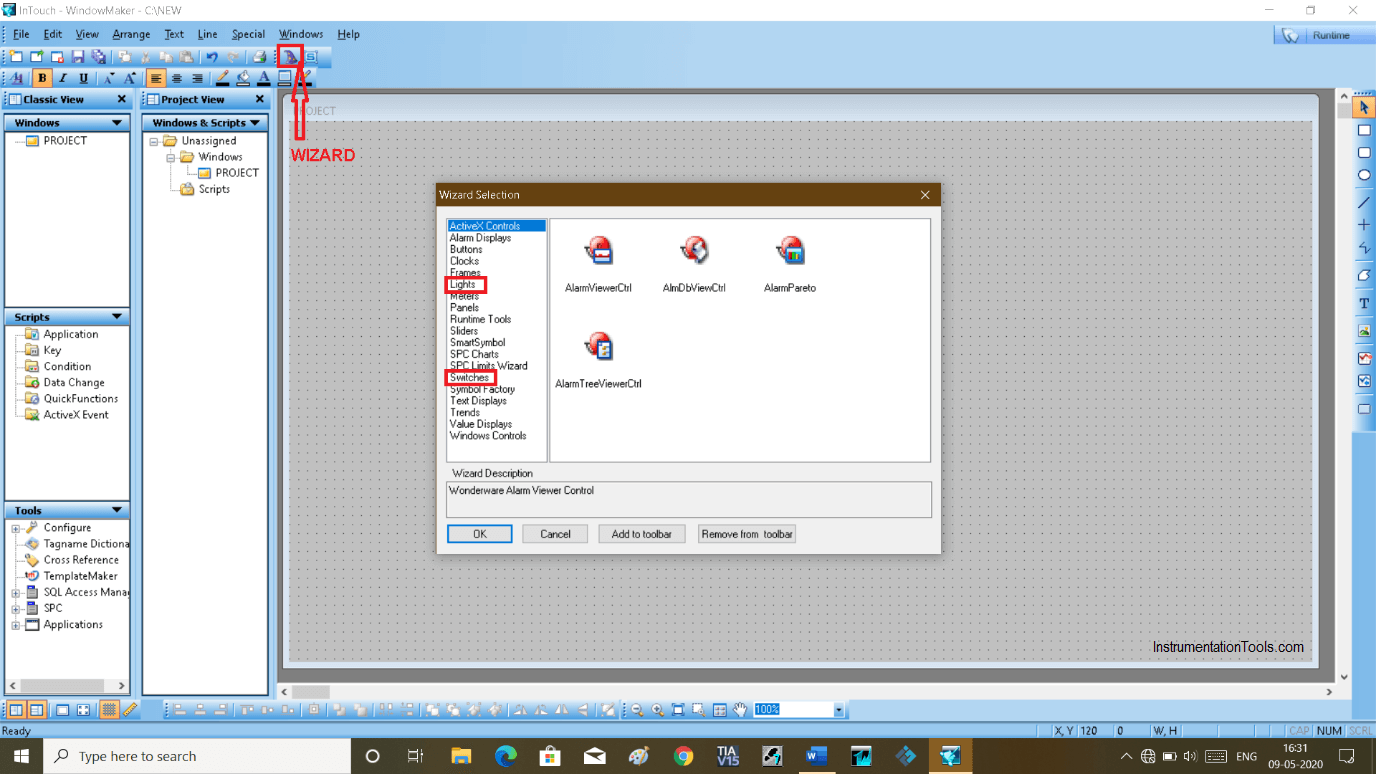
Step 2:
Go to the wizard as shown in the below window. And add a switch and lights. As we are using six logic gates we will add twelve switches and six lamps.
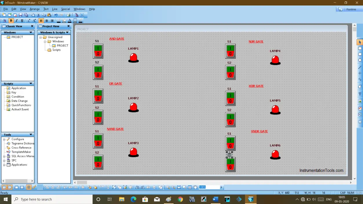
Step 3:
Add all the objects as shown in the below window. Give tag name as per text. Do read my article on it.
Step 4:
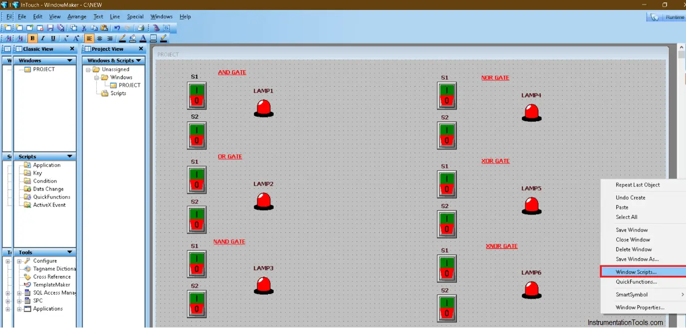
Right-click on the display as shown in the below window. Select “windows script”.
Step 5:
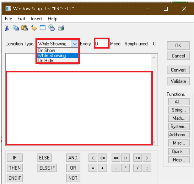
The following scripting window will open. Select condition type. In “on a show” it will always remain starting condition.
In “while showing” option, we have to write a script to operate switch and lamp. Also, select every and enter some time in it.
Step 6:
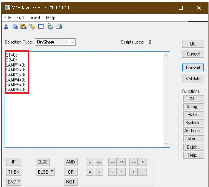
Here, I have added an initial condition as shown below. It always remains zero.
Step 7:
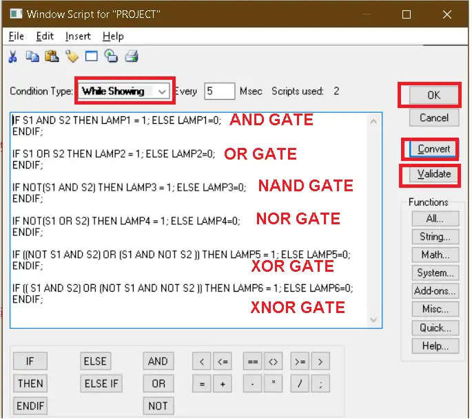
In “while showing” I have written condition to turn OFF and ON gate, based on the type of logic gate and lamp will turn ON accordingly.
Step 8:
After writing down condition click on “validate” than “convert” and then hit “ok”.
To test the logic click on “runtime” located on the top right of the below.
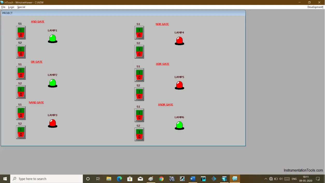
Step 9:
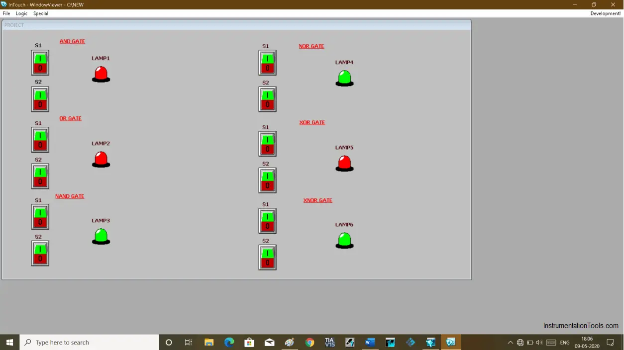
When switches are OFF NAND, NOR AND XNOR gates will remain ON.
Step 10:
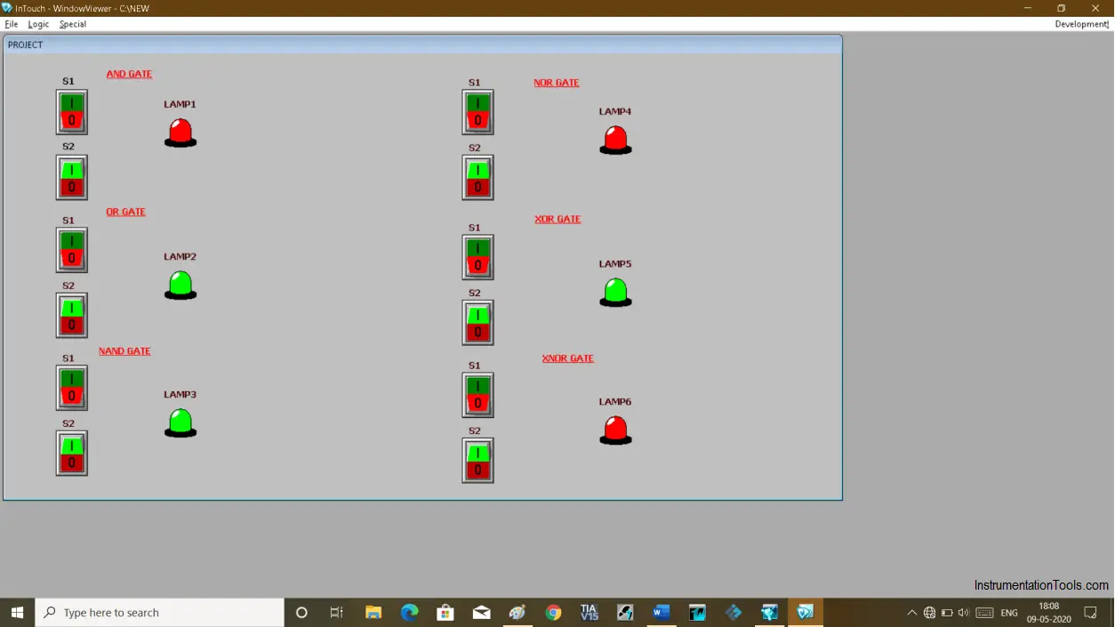
When S1 is ON then OR, NAND, and XOR gate’s lamp will turn ON.
Step 11:
When S2 is ON then OR, NAND, and XOR gate’s lamp will turn ON.
Step 12:
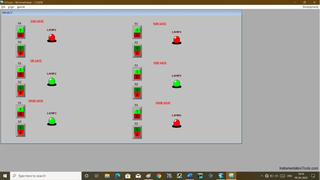
When both S1 and S2 are ON then the lamp of AND, OR and XNOR will turn ON.
Author: Suhel Patel
If you liked this article, then please subscribe to our YouTube Channel for PLC and SCADA video tutorials.
You can also follow us on Facebook and Twitter to receive daily updates.
Read Next:
- Quiz Questions on Motors
- Modifying PLC Programs
- Field instrument to Control Room
- What is SCADA System?
- Siemens Profinet Configuration