Gate valves are available with a variety of disks. Classification of gate valves is usually made by the type disk used: solid wedge, flexible wedge, split wedge, or parallel disk.
Classification of Gate Valves
Solid wedges, flexible wedges, and split wedges are used in valves having inclined seats. Parallel disks are used in valves having parallel seats.
Regardless of the style of wedge or disk used, the disk is usually replaceable. In services where solids or high velocity may cause rapid erosion of the seat or disk, these components should have a high surface hardness and should have replacement seats as well as disks.
If the seats are not replaceable, seat damage requires removal of the valve from the line for refacing of the seat, or refacing of the seat in place. Valves being used in corrosion service should normally be specified with replaceable seats.
Solid Wedge Gat
The solid wedge gate valve shown in below Figure is the most commonly used disk because of its simplicity and strength.

Figure : Solid Wedge Gate Valve
A valve with this type of wedge may be installed in any position and it is suitable for almost all fluids. It is practical for turbulent flow.
Flexible Wedge Gate Valve
The flexible wedge gate valve illustrated in below Figure is a one-piece disk with a cut around the perimeter to improve the ability to match error or change in the angle between the seats. The cut varies in size, shape, and depth.
A shallow, narrow cut gives little flexibility but retains strength. A deeper and wider cut, or cast-in recess, leaves little material at the center, which allows more flexibility but compromises strength.

Figure : Flexible Wedge Gate Valve
A correct profile of the disk half in the flexible wedge design can give uniform deflection properties at the disk edge, so that the wedging force applied in seating will force the disk seating surface uniformly and tightly against the seat.
Gate valves used in steam systems have flexible wedges. The reason for using a flexible gate is to prevent binding of the gate within the valve when the valve is in the closed position.
When steam lines are heated, they expand and cause some distortion of valve bodies. If a solid gate fits snugly between the seat of a valve in a cold steam system, when the system is heated and pipes elongate, the seats will compress against the gate and clamp the valve shut.
This problem is overcome by using a flexible gate, whose design allows the gate to flex as the valve seat compresses it.
The major problem associated with flexible gates is that water tends to collect in the body neck. Under certain conditions, the admission of steam may cause the valve body neck to rupture, the bonnet to lift off, or the seat ring to collapse. Following correct warming procedures prevent these problems.
Split wedge Gate Valve
Split wedge gate valves, as shown in below Figure, are of the ball and socket design. These are self-adjusting and self-aligning to both seating surfaces.
The disk is free to adjust itself to the seating surface if one-half of the disk is slightly out of alignment because of foreign matter lodged between the disk half and the seat ring.

Figure : Split Wedge Gate Valve
This type of wedge is suitable for handling non-condensing gases and liquids at normal temperatures, particularly corrosive liquids.
Freedom of movement of the disk in the carrier prevents binding even though the valve may have been closed when hot and later contracted due to cooling. This type of valve should be installed with the stem in the vertical position.
Parallel Disk Gate Valve
The parallel disk gate valve illustrated in below Figure is designed to prevent valve binding due to thermal transients. This design is used in both low and high pressure applications.
The wedge surfaces between the parallel face disk halves are caused to press together under stem thrust and spread apart the disks to seal against the seats.
The tapered wedges may be part of the disk halves or they may be separate elements. The lower wedge may bottom out on a rib at the valve bottom so that the stem can develop seating force. In one version, the wedge contact surfaces are curved to keep the point of contact close to the optimum.
In other parallel disk gates, the two halves do not move apart under wedge action. Instead, the upstream pressure holds the downstream disk against the seat. A carrier ring lifts the disks, and a spring or springs hold the disks apart and seated when there is no upstream pressure.
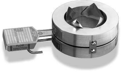
Another parallel gate disk design provides for sealing only one port. In these designs, the high pressure side pushes the disk open (relieving the disk) on the high pressure side, but forces the disk closed on the low pressure side. With such designs, the amount of seat leakage tends to decrease as differential pressure across the seat increases.
These valves will usually have a flow direction marking which will show which side is the high pressure (relieving) side. Care should be taken to ensure that these valves are not installed backwards in the system.

Figure : Parallel Disk Gate Valve
Some parallel disk gate valves used in high pressure systems are made with an integral bonnet vent and bypass line.
A three-way valve is used to position the line to bypass in order to equalize pressure across the disks prior to opening. When the gate valve is closed, the three-way valve is positioned to vent the bonnet to one side or the other.
This prevents moisture from accumulating in the bonnet. The three-way valve is positioned to the high pressure side of the gate valve when closed to ensure that flow does not bypass the isolation valve.
The high pressure acts against spring compression and forces one gate off of its seat. The three-way valve vents this flow back to the pressure source.
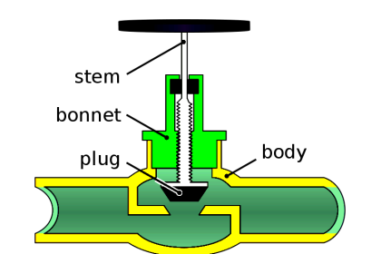
Gate Valve Stem Design
Gate valves are classified as either rising stem or non-rising stem valves. For the non-rising stem gate valve, the stem is threaded on the lower end into the gate.
As the hand wheel on the stem is rotated, the gate travels up or down the stem on the threads while the stem remains vertically stationary.
This type valve will almost always have a pointer-type indicator threaded onto the upper end of the stem to indicate valve position. Figures 2 and 3 illustrate rising-stem gate valves and non-rising stem gate valves.
The non-rising stem configuration places the stem threads within the boundary established by the valve packing out of contact with the environment. This configuration assures that the stem merely rotates in the packing without much danger of carrying dirt into the packing from outside to inside.
Also See : Gate Valve Animation
Rising stem gate valves are designed so that the stem is raised out of the flow-path when the valve is open. Rising stem gate valves come in two basic designs. Some have a stem that rises through the handwheel while others have a stem that is threaded to the bonnet.
Gate Valve Seat Design
Seats for gate valves are either provided integral with the valve body or in a seat ring type of construction.
Seat ring construction provides seats which are either threaded into position or are pressed into position and seal welded to the valve body. The latter form of construction is recommended for higher temperature service.
Integral seats provide a seat of the same material of construction as the valve body while the pressed-in or threaded-in seats permit variation. Rings with hard facings may be supplied for the application where they are required.
Small, forged steel, gate valves may have hard faced seats pressed into the body. In some series, this type of valve in sizes from 1/2 to 2 inches is rated for 2500 psig steam service.
In large gate valves, disks are often of the solid wedge type with seat rings threaded in, welded in, or pressed in. Screwed in seat rings are considered replaceable since they may be removed and new seat rings installed.