Inst ToolsInst ToolsInst Tools
  • Courses
  • Automation
    • PLC
    • Control System
    • Safety System
    • Communication
    • Fire & Gas System
  • Instrumentation
    • Design
    • Pressure
    • Temperature
    • Flow
    • Level
    • Vibration
    • Analyzer
    • Control Valve
    • Switch
    • Calibration
    • Erection & Commissioning
  • Interview
    • Instrumentation
    • Electrical
    • Electronics
    • Practical
  • Q&A
    • Instrumentation
    • Control System
    • Electrical
    • Electronics
    • Analog Electronics
    • Digital Electronics
    • Power Electronics
    • Microprocessor
  • Request
Search
  • Books
  • Software
  • Projects
  • Process
  • Tools
  • Basics
  • Formula
  • Power Plant
  • Root Cause Analysis
  • Electrical Basics
  • Animation
  • Standards
  • 4-20 mA Course
  • Siemens PLC Course
Reading: How to Interchange ON Delay Timer and OFF Delay Timer in a PLC
Share
Font ResizerAa
Inst ToolsInst Tools
Font ResizerAa
  • Courses
  • Design
  • PLC
  • Interview
  • Control System
Search
  • Courses
  • Automation
    • PLC
    • Control System
    • Safety System
    • Communication
    • Fire & Gas System
  • Instrumentation
    • Design
    • Pressure
    • Temperature
    • Flow
    • Level
    • Vibration
    • Analyzer
    • Control Valve
    • Switch
    • Calibration
    • Erection & Commissioning
  • Interview
    • Instrumentation
    • Electrical
    • Electronics
    • Practical
  • Q&A
    • Instrumentation
    • Control System
    • Electrical
    • Electronics
    • Analog Electronics
    • Digital Electronics
    • Power Electronics
    • Microprocessor
  • Request
Follow US
All rights reserved. Reproduction in whole or in part without written permission is prohibited.
Inst Tools > Blog > PLC Tutorials > How to Interchange ON Delay Timer and OFF Delay Timer in a PLC

How to Interchange ON Delay Timer and OFF Delay Timer in a PLC

Last updated: March 4, 2021 3:56 pm
Editorial Staff
PLC Tutorials
2 Comments
Share
4 Min Read
SHARE

Timer functions are most important in PLC Programming. Logics play the important role in PLC Programming.

Contents
ON Delay Timer and OFF Delay TimerPLC Timer FunctionsON DELAY TIMER :OFF DELAY TIMER :List of Inputs and OutputsPLC Program for ON Delay and OFF Delay TimersLadder Logic DescriptionConclusion

According to PLC programmer’s skills, logic will get different in application. In this program, we are going to interchange the function of On Delay Timer and Off Delay timer. AB RSLogix 500 is used to implement the concepts.

ON Delay Timer and OFF Delay Timer

Interchange ON Delay Timer and OFF Delay Timer

PLC Timer Functions

ON DELAY TIMER :

In Layman Statement, Delaying the turning “ON” of the output is On Delay Timer.

Example :

See the image below; if you turn on Input, after 5 sec output will get turn on. It will not turn on immediately.
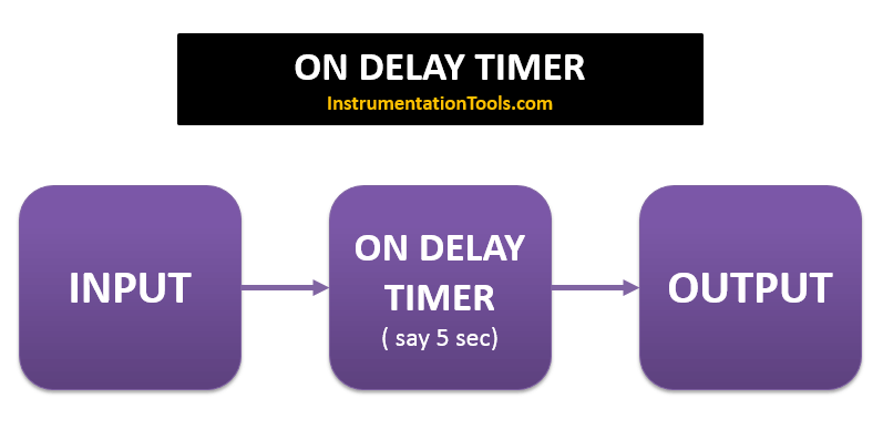
PLC ON DELAY TIMER FUNCTION

In AB PLC, ON Delay Timer is having 6 parameters.

They are

  • Enable Bit (EN): It will turn on when timer is on
  • Done Bit (DN): It will turn on once the timer accumulator value reaches preset value
  • Timer Timing bit (TT) : This bits enable when timer accumulator value is running
  • Preset (PRE): Integer value to set how long timer needs to run or limit starting from zero.
  • Accumulator (ACC): Running value of the timer
  • Time Base : You have options to chose timer base, Sec, cent sec, Mille sec.

OFF DELAY TIMER :

In Layman Statement, Delaying the turning “OFF” of the output is Off Delay Timer.

Example:

See the image below; if you turn on Input, output will turn ON immediately, when you turn OFF the input, It will take 5 sec to turn OFF the output. It will not turn OFF immediately.
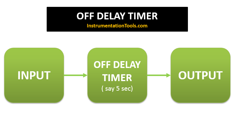
PLC OFF DELAY TIMER FUNCTION

In AB PLC, OFF Delay Timer is having 6 parameters.

They are

  • Enable Bit (EN): It will turn on when timer is on
  • Done Bit (DN): It will turn on once the timer is On and remains ON until timer accumulator value reaches preset value
  • Timer Timing bit (TT) : This bits enable when timer accumulator value is running
  • Preset (PRE): Integer value to set how long timer needs to run or limit starting from zero.
  • Accumulator (ACC): Running value of the timer
  • Time Base: You have options to choose timer base, Sec, cent sec, Millie sec.

List of Inputs and Outputs
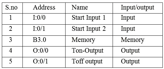
PLC Timer Logic Inputs Outputs

PLC Program for ON Delay and OFF Delay Timers
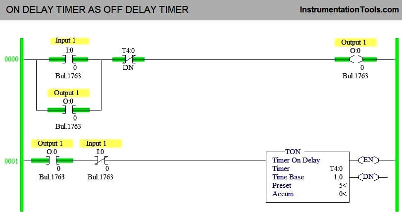
ON DELAY TIMER AS OFF DELAY TIMER
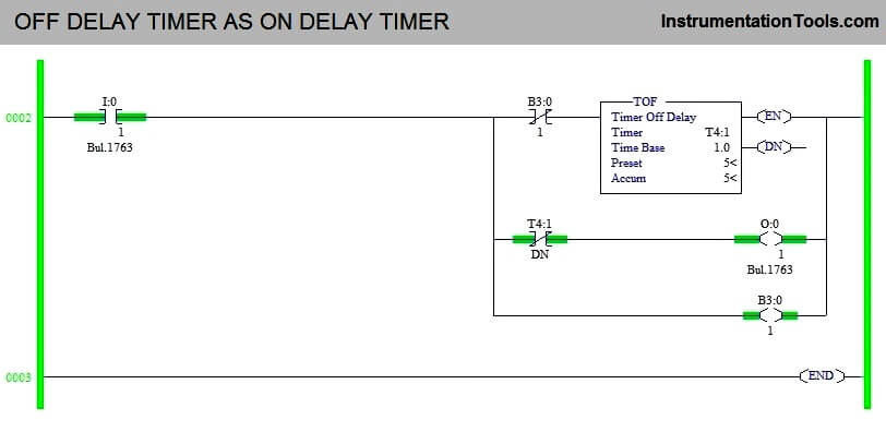
OFF DELAY TIMER AS ON DELAY TIMER

Ladder Logic Description

ON DELAY TIMER AS OFF DELAY TIMER :

1. Rung 0000 :-

Latching is done using output coil to stay ON even Input is turned off. Normally closed timer done bit is used to turn off the output once timer accumulator value reach preset and that make TON to act as TOFF.

2. Rung 0001 :-

since the Start Input is used as normally closed input, Output Coil is attached as interlocking, so that it won’t turn on timer at the beginning of the program.

OFF DELAY TIMER AS ON DELAY TIMER :

3. Rung 0003 :-

Input 2 turned to turn on timer, Memory coil is used to trigger the timer to start count and to make TOFF to act as TON.

Conclusion

The above used timer concept is used to under the function of timer working. It may or may not used in real time application.

Author : Hema Deepan

If you liked this article, then please subscribe to our YouTube Channel for PLC and SCADA video tutorials.

You can also follow us on Facebook and Twitter to receive daily updates.

Read Next:
MCQ on PLC Test

Compare PLC and DCS

What is Relay Logic ?

PLC Maintenance List

Boiler PLC Start-up

Don't Miss Our Updates
Be the first to get exclusive content straight to your email.
We promise not to spam you. You can unsubscribe at any time.
Invalid email address
You've successfully subscribed !

Continue Reading

Process Interlocks and Trips
Free SCADA Training Course
PLC Practice Questions
How to Work with Allen Bradley RsLogix Emulator?
Siemens S7 300 and STEP 7 PLC program using SIMATIC Software
PLC Analog Input Card Resolution Effects on Accuracy
Share This Article
Facebook Whatsapp Whatsapp LinkedIn Copy Link
Share
2 Comments
  • SNEHIL SHUKLA says:
    March 31, 2022 at 9:31 pm

    There are two lamp on pressing the start push button the first lamp should go on when the start push button is press again the first lamp should go off and the second lamp should go on if any of the lamp is on for more than 15 second they both the lamp will interchange their status ? Please solve this problem ?

    Reply
  • SNEHIL SHUKLA says:
    March 31, 2022 at 9:32 pm

    How will we be interchange their status?

    Reply

Leave a Reply Cancel reply

Your email address will not be published. Required fields are marked *

Stay Connected

128.3kFollowersLike
69.1kFollowersFollow
210kSubscribersSubscribe
38kFollowersFollow

Categories

Explore More

Site Commissioning Steps for PLC Programmers
XG5000 Example of Simple Conveyor Control PLC Program
PLC Alarm and Trip Documentation
Configuration of InTouch Scada Trends
Smart Automation Solutions: PLC Logic for Stairway Lighting
How to Simplify PLC Coding Using Karnaugh Maps?
Pause the Timer PLC Ladder Logic
STAR-DELTA Auto And Manual Program using XG5000 Software

Keep Learning

PLC Program to Control Motor Speed using VFD Drive

Motor Speed Control using VFD and PLC Programming

What is an RTU - Remote Terminal Unit

What is an RTU? – Remote Terminal Unit

Download Free Robotics Software

Step by Step Guidelines to Download Free Robotics Software

PLC Compressor Control Ladder Logic

PLC Compressor Control Ladder Logic

Free Download PLC Book

Free Download Programmable Logic Controller (PLC) Book

PLC Motor Control Circuit

Motor Trip Logic using PLC Programming

Shift Bit Register in PLC

Shift Bit Register in PLC

Two Hand Control Logic

Two Hand Control Logic using PLC

Learn More

Electric Motor Actuator Parts

Electric Motor Actuator Parts

GC sample loop

Chromatograph Sample Valves

Classic Control Circuits

Motor Classic Control Circuits using Single Push button

Add an alarm display to the graphics.

How to Configure an Alarm in InTouch SCADA?

Open Tank Interface Level measurement principle

Open Tank Interface Level Measurement

Thermocouple cold junction compensation

Why Thermocouple Reference Junction Compensation Required ?

Basics of Trips, Interlocks, Permissives & Sequences

Basics of Trips, Interlocks, Permissives & Sequences

Ion Spectrometers Questions & Answers

Electron Spectroscopy for Chemical Analysis

Menu

  • About
  • Privacy Policy
  • Copyright

Quick Links

  • Learn PLC
  • Helping Hand
  • Part Time Job

YouTube Subscribe

Follow US
All rights reserved. Reproduction in whole or in part without written permission is prohibited.
Welcome Back!

Sign in to your account

Username or Email Address
Password

Lost your password?