Additional requirements for instrumentation bulk material in Oxygen service and other clean process fluid service in an air separation unit.
We shall hereby discuss minimum requirements for the selection of non-metallic components and for the cleaning of instrumentation bulk material items with process wetted surfaces (e.g. tubing, fittings, instrument manifolds, gauge valves) that are used in the following subsystems: All Process related subsystems.
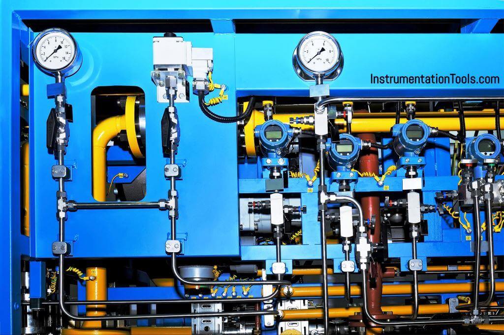
The respective Hook-up drawing identifies the items that are subject to the requirements of this document.
It is of prime importance for the reduction of fire hazards in Air Separation Units (ASU), that all process wetted surfaces in oxygen systems are kept free from contaminants – non-volatile residues and particles – and components that are not oxygen compatible.
To this end, cleaning of all surfaces must be carried out in an appropriate and traceable way wherever contamination may be presumed.
After cleaning, suitable packaging and marking of the components is necessary to avoid recontamination or inadvertent misdirection of material.
Non-metallic components must be compatible with oxygen for all permissible process conditions.
Instruments Cleaning Methods and Procedures
The MANUFACTURER of the items must select an appropriate cleaning method and furnish a written procedure for the cleaning process and the subsequent verification thereof.
Among other technical aspects, the nature and material of the components to be cleaned as well as the contaminants must be considered as well as safety and environmental aspects.
The methods and procedures must be furnished by qualified technical personnel and should be well proven for the cleaning of similar components in oxygen service.
A quality management system must be in a place that ensures the diligent application of the cleaning procedures. The cleaning must be integrated into the manufacturing process in such a way as to avoid any contamination of the components after cleaning.
Complete removal of cleaning agents, adequate rinsing, and drying must be ensured by the procedures.
The cleaning process must in no case have any detrimental effect on the integrity, properties or functionality of the components. Chemical cleaning agents should be oxygen-compatible, noncorrosive towards the materials of construction and not leave behind any residue.
Reference is made to ASTM G93-03 and EIGA IGC 33/03/E that provide guidance for the selection of appropriate cleaning methods. Wherever surfaces are inaccessible for cleaning after manufacturing, the manufacturing process must inherently render contamination impossible.
In this case, the MANUFACTURER shall provide his manufacturing procedures for approval to the PURCHASER.
Acceptance Criteria for the Cleanliness
The cleaning procedures must be suitable to achieve a level of non-volatile residue which corresponds to Level C of ASTM G93-03 – 6mg/ft² (66 mg/m²) – and a maximum particle population corresponding to Level 300 of ASTM G93-03 – maximum particle size <300μm.
Instruments Cleanliness Verification
Along with the cleaning procedures, the MANUFACTURER must establish written procedures to ensure the verification of the cleaning process.
The procedures must be furnished by qualified technical personnel and should be well proven for the cleaning verification of components in oxygen service.
A quality management system must be in place that ensures diligent application of the procedures. A quantitative verification shall be carried out to initially qualify the cleaning procedures.
Subsequent quantitative verification may be applied to randomly selected representative components to reassess the effectiveness of the cleaning procedures.
Once the cleaning procedures are implemented and established, the cleanliness may be verified by ensuring thorough adherence to the cleaning procedures augmented by qualitative verification.
As a minimum, visual inspection under white light or UV light shall be carried out at 100% of the cleaned items. Where surfaces are not accessible for visual inspection, a wipe test shall be carried out.
All verification steps shall be carried out by qualified and trained personnel. The verification and subsequent material handling must not compromise the cleanliness of the components.
Reference is made to ASTM G93-03 and EIGA IGC 33/03/E that provide guidance for the cleanliness verification.
Material Selection
All non-metallic materials of process wetted parts must be tested and certified as oxygen compatible by an accredited laboratory.
The test and certification must cover the entire range of the mechanical design of the item. ASTM G63-99 may be referred to for guidance on evaluating non-metallic materials for oxygen service.
Packaging and Labeling
After cleaning and cleanliness verification, the items shall immediately be packaged appropriately to avoid recontamination during material handling at the workshop, during transport and at site. Caps, plugs and bags or films made of polyethylene shall be used for effective sealing.
The cleaning method and level shall be identified on a label that is affixed to the component. Additionally, a note shall be applied
“CLEANED FOR OXYGEN SERVICE DO NOT OPEN UNTIL READY FOR INSTALLATION”
Packaging and labelling shall be carried out in accordance with ASTM G93-03.
Cleanliness during Construction and Pre-commissioning
It is of utmost importance to avoid recontamination of the cleaned components during construction.
General precautions as described in ASTM G93-03, EIGA IGC 33/06/E, and appropriate procedures must be in place and must be strictly followed.
Protective packaging of cleaned components should be opened as late as practicably feasible before installation.
During and after installation of the components, care must be taken to avoid ingress of contaminants or moisture into the process wetted system (unused openings shall be left plugged, etc.).
While cleaning of pipelines in the pre-commissioning phase, recontamination of instrument tubing must be avoided by adequate means.
Special care must be taken to avoid misdirection of components that might lead to a mix up of cleaned items with similar but un-cleaned items.
Documentation
Upon request, the MANUFACTURER shall be in a position to provide the following documentation:
Cleaning Procedures for the components.
Certification of oxygen compatibility for all non-metallic components and lubricants – for the entire range of design conditions.
Verification Procedures for the cleaning steps of the components.
Documentation of the Quality Management System.
Report on cleaning and verification for the individual components that are part of the Purchase Order.
Material Safety Data Sheet of the chemical agents used in the Procedures.
Referenced Documents
- ASTM G63-99 STANDARD GUIDE FOR EVALUATING NONMETALLIC MATERIALS FOR OXYGEN SERVICE
- ASTM G93-03 STANDARD PRACTICE FOR CLEANING METHODS AND CLEANLINESS. LEVELS FOR MATERIAL AND EQUIPMENT USED IN OXYGEN-ENRICHED ENVIRONMENTS
- EIGA IGC 33/06/E CLEANING OF EQUIPMENT FOR OXYGEN SERVICE – GUIDELINE
Definitions and Acronyms
ASU – Air Separation Unit
LOX – Liquid Oxygen
LIN – Liquid Nitrogen
For further definitions of the terminology refer to ASTM G93-03 and EIGA IBC 33/06/E.
Read Next:
