Inst ToolsInst ToolsInst Tools
  • Courses
  • Automation
    • PLC
    • Control System
    • Safety System
    • Communication
    • Fire & Gas System
  • Instrumentation
    • Design
    • Pressure
    • Temperature
    • Flow
    • Level
    • Vibration
    • Analyzer
    • Control Valve
    • Switch
    • Calibration
    • Erection & Commissioning
  • Interview
    • Instrumentation
    • Electrical
    • Electronics
    • Practical
  • Q&A
    • Instrumentation
    • Control System
    • Electrical
    • Electronics
    • Analog Electronics
    • Digital Electronics
    • Power Electronics
    • Microprocessor
  • Request
Search
  • Books
  • Software
  • Projects
  • Process
  • Tools
  • Basics
  • Formula
  • Power Plant
  • Root Cause Analysis
  • Electrical Basics
  • Animation
  • Standards
  • 4-20 mA Course
  • Siemens PLC Course
Reading: Input-Output Relationships of Transmitters
Share
Font ResizerAa
Inst ToolsInst Tools
Font ResizerAa
  • Courses
  • Design
  • PLC
  • Interview
  • Control System
Search
  • Courses
  • Automation
    • PLC
    • Control System
    • Safety System
    • Communication
    • Fire & Gas System
  • Instrumentation
    • Design
    • Pressure
    • Temperature
    • Flow
    • Level
    • Vibration
    • Analyzer
    • Control Valve
    • Switch
    • Calibration
    • Erection & Commissioning
  • Interview
    • Instrumentation
    • Electrical
    • Electronics
    • Practical
  • Q&A
    • Instrumentation
    • Control System
    • Electrical
    • Electronics
    • Analog Electronics
    • Digital Electronics
    • Power Electronics
    • Microprocessor
  • Request
Follow US
All rights reserved. Reproduction in whole or in part without written permission is prohibited.
Inst Tools > Blog > Formulas > Input-Output Relationships of Transmitters

Input-Output Relationships of Transmitters

Last updated: April 19, 2019 1:19 pm
Editorial Staff
Formulas
6 Comments
Share
6 Min Read
SHARE

Have you ever had that actually forget something simple? And generally forgotten it was in the form like a formula. For example, the formula to convert temperature unit of degrees Celsius to degrees Fahrenheit. Generally we use the formula:

{(9/5) * x + 32 ° F}

Where “x”  is the temperature in Deg C

So as to know how to calculate ° F of the temperature of 50 ° C, if using the above formula to

{(9/5) * x + 32 ° F} = {(9/5) * 50 ° F} + 32 = 122 ° F

Easy enough right? Yes, if we memorized formula. The problem is if we completely forgot the formula.

The calculation of input-output relationships of transmitter

input-output-relationships-of-transmitters

Something similar may happen when we’re doing calibration, like a pressure transmitter. For example, with an input pressure of 0-300 PSI and 4-20mA output.

If we use the method of 5-point calibration (0%, 25%, 50%, 75% and 100%), it may be quite easy for us, it should be how we put pressure on the transmitter at the time of testing at 50% (12mA). But it is different if we verify the pressure transmitter is already on-line with different process value.

For example, we find the pressure on the input side of the transmitter is 235 PSI, then what is the pressure transmitter output signal?

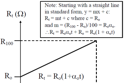
Back to the issue of conversion of temperature. If we forget the formula, we can actually do the conversion without having memorized the formula, the condition we know the upper limit and lower limit for the second unit. Then, using the equation of general comparison, we can create their own respective formula.

We know that the units Celsius has a measuring range (measuring scale for the calculation) between 0-100 ° C and Fahrenheit 32-212 ° F. So if asked, 50 ° C was how ° F, then:

Temperature Transmitter Formula

See calculation above, it may be longer than we memorize the formula, here we do not try to memorize formulas, but understand the concept, because the first formula above were true simplification of calculations a second.

The concept of how it mean? This calculation is a calculation of comparison, to compare two different scales.

Let’s agree that:

x ° C = value ° C

C min   = minimum scale ° C = 0 ° C

C max  = maximum scale ° C = 100 ° C

x ° F = value ° F

F min  = minimum scale ° F = 32 ° F

F max maximum scale ° F = 212 ° F

thus:

Temperature Transmitter Conversion Formula

Using the above equation:

Temperature Transmitter Conversion Example

This applies to calculate the output of a transmitter at the time of a particular input. For example, as the above example, we have a pressure transmitter with 0-300 PSI pressure input range and output 4-20mA.

Let’s agree:

x in   = value transmitter input (235PSI)

In min   = scale of minimum input transmitter = 0PSI

In max   = maximum scale transmitter input = 300PSI

x out = transmitter output value (mA)

Out min   = minimum scale transmitter output = 4mA

Out max = maximum scale = 20mA transmitter output

With reference to the equation of comparison, the value of 235PSI input transmitter can be calculated:

Temperature Transmitter Calculation

By understanding the concept of the above, we can make a generic equation for the relation between the input and output of a transmitter as follows:

Temperature Transmitter Formulae

Where:

x dit   = value in question (want to know)

dit min   = minimum scale range in question

dit max   = maximum scale range in question = 300PSI

x dik = value unknown

dik min   = minimum scale of a range of known

dik max = maximum scale of the known range

Example:

A temperature transmitter with an input range +50 to 200 ° F and output range is 4-20mA. what is the output if input temperature is 61 ° F:

dit min   = 4

dit max   = 20

x dik = 61

dik min   = 50

dik max  = 200

Then:

Temperature Transmitter Convert

Thus, the input temperature of 61 ° F, the transmitter output is 5.1737 mA

Thus, a generic formula for calculating the relationship of input and output transmitter or vice versa, can use:

Temperature Transmitter Formulae

A temperature transmitter with input range -25 to 100 ° C and output 4-20mA range, Transmitter output is 17.5 mA, and find out temperature reading ?

Try to calculate the answer using above method:

Share your comments

Articles You May Like :

Level Control Loop Tuning

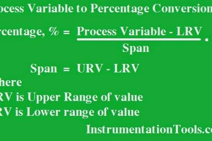
Percentage to Process Variable

Transmitter Process Variable

Control Valve Cv calculation

Radar Level Transmitter

Don't Miss Our Updates
Be the first to get exclusive content straight to your email.
We promise not to spam you. You can unsubscribe at any time.
Invalid email address
You've successfully subscribed !

Continue Reading

Instrument Percent of Span Error
Formulas to calculate mA from PV, LRV and URV
Closed Tank Remote Seal Capillary type DP Transmitter
Formula to Calculate 3-15psi from 4-20mA Current
4-20mA Formulas and Examples
Calculate Process Variable from Transmitter Current
Share This Article
Facebook Whatsapp Whatsapp LinkedIn Copy Link
Share
6 Comments
  • Venkat says:
    November 21, 2016 at 8:23 am

    Was very useful. Can’t believe how we think of simple things as complicated ones. Thanks.

    Reply
  • kingsley says:
    November 21, 2016 at 1:35 pm

    Thanks sir , you are great !!! your informations are powerfull.

    Please explain how to calibrate FF temperature and pressure transmitter using field communicator

    Reply
  • Nagaraju says:
    November 25, 2016 at 3:12 pm

    Thank u sir.

    Reply
  • kudo says:
    December 17, 2018 at 7:10 am

    may I know what is the answer sir?

    Reply
  • kudo says:
    December 17, 2018 at 7:31 am

    I get 80.47 deg C, is it true?

    Reply
    • S Bharadwaj Reddy says:
      December 17, 2018 at 8:01 am

      Yes, Correct. You can try online Inst Cal for cross checking. Click Here.

      Reply

Leave a Reply Cancel reply

Your email address will not be published. Required fields are marked *

Stay Connected

128.3kFollowersLike
69.1kFollowersFollow
210kSubscribersSubscribe
38kFollowersFollow

Categories

Explore More

DP Level Transmitter Elevation and Suppression Corrections
Formula to Calculate 4-20ma from Percentage
Remote Seal Transmitters Ranging Calculation
Standard 4 to 20 mA Conversion Formula
PLC Analog Input Conversion Formula
Calculate Process Variable from 4-20mA using Fraction of Measurement
Turbine Flow Meter Coefficient and Scaling Factor
Formula for Linear % to Square root % conversion

Keep Learning

Closed Tank Level Measurement Formula

Siemens Differential Pressure Transmitter Calculations (Flange Type)

PLC Raw Count Calculation formula for Pressure Transmitter

PLC Raw Count Calculation for Pressure Transmitter

Open Tank DP Level Measurement

Open Tank DP Level Transmitter Calculations

4-20mA VFD Drive Formula

4-20mA Linear Conversion Calculation for VFD Drive (Formula)

Control valve positioner calculation

Calculate Control Valve Stem Position

Zero Suppression in level Measurement

Zero Suppression and Zero Elevation Calculations

DP Transmitter Level Measurement for Closed Tank Wet leg Method

DP Transmitter Dry Leg & Wet Leg Calculations

Temperature Transmitter Formula

Calculate Temperature Transmitter Output

Learn More

Instrumentation Commissioning

Commissioning Documents for Instrumentation Engineers

RTD Construction

Introduction to RTDs

AND Logic in Bently Nevada Vibration System

AND Logic in Bently Nevada Vibration System

WirelessHART Device Terminals

WirelessHART Network Gateway Device

What is Swing Check Valve ?

HART Transmitters Loop Checks

Loop Check of 4-20mA or HART Transmitters

Sorting and Counting Products on Conveyors by Color

PLC Programming for Multi-Color Sorting Conveyor System

Simple Loop with Local Indication

Instrument Loop Test Requirements and Operation Procedures

Menu

  • About
  • Privacy Policy
  • Copyright

Quick Links

  • Learn PLC
  • Helping Hand
  • Part Time Job

YouTube Subscribe

Follow US
All rights reserved. Reproduction in whole or in part without written permission is prohibited.
Welcome Back!

Sign in to your account

Username or Email Address
Password

Lost your password?