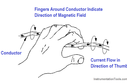
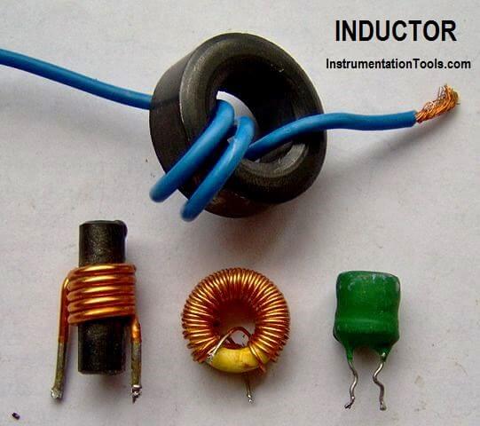
An inductor is a circuit element that will store electrical energy in the form of a magnetic field. It is usually a coil of wire wrapped around a core of permeable material. The magnetic field is generated when current is flowing through the wire.
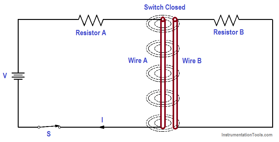
If two circuits are arranged as in Figure 1, a magnetic field is generated around Wire A, but there is no electromotive force (EMF) induced into Wire B because there is no relative motion between the magnetic field and Wire B.
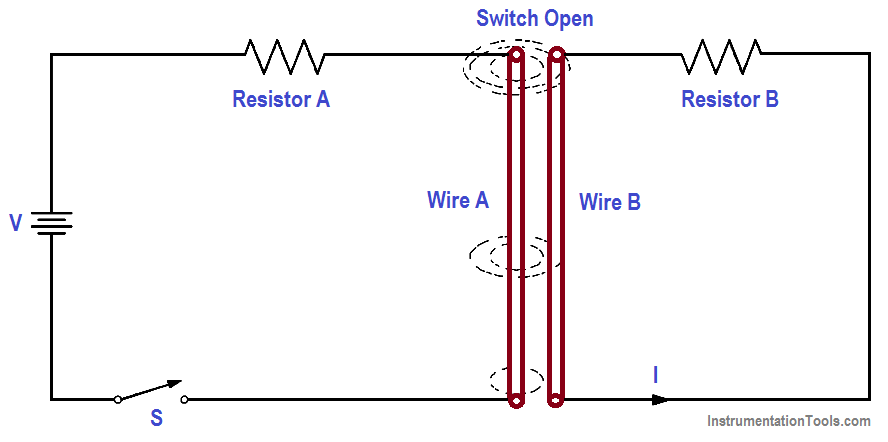
If we now open the switch, the current stops flowing in Wire A, and the magnetic field collapses. As the field collapses, it moves relative to Wire B. When this occurs, an EMF is induced in Wire B.
Figure 1a : Magnetic Field Around a Wire Remains Constant
Figure 1b : Magnetic Field Around a Wire Collapsing
Figure 1 (a & b) : Induced EMF
This is an example of Faraday’s Law, which states that a voltage is induced in a conductor when that conductor is moved through a magnetic field, or when the magnetic field moves past the conductor. When the EMF is induced in Wire B, a current will flow whose magnetic field opposes the change in the magnetic field that produced it.
For this reason, an induced EMF is sometimes called counter EMF or CEMF. This is an example of Lenz’s Law, which states that the induced EMF opposes the EMF that caused it.
The three requirements for inducing an EMF are:
- a conductor,
- a magnetic field, and
- relative motion between the two.
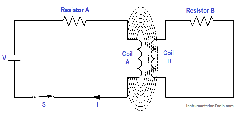
Figure 2 : Induced EMF in Coils
The faster the conductor moves, or the faster the magnetic field collapses or expands, the greater the induced EMF. The induction can also be increased by coiling the wire in either Circuit A or Circuit B, or both, as shown in Figure 2.
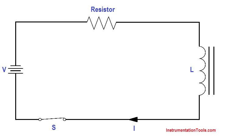
Self-induced EMF is another phenomenon of induction. The circuit shown in Figure 3 contains a coil of wire called an inductor (L). As current flows through the circuit, a large magnetic field is set up around the coil. Since the current is not changing, there is no EMF produced. If we open the switch, the field around the inductor collapses. This collapsing magnetic field produces a voltage in the coil. This is called self-induced EMF.
Figure 3 : Self-Induced EMF
The polarity of self-induced EMF is given to us by Lenz’s Law. The polarity is in the direction that opposes the change in the magnetic field that induced the EMF. The result is that the current caused by the induced EMF tends to maintain the same current that existed in the circuit before the switch was opened. It is commonly said that an inductor tends to oppose a change in current flow.
The induced EMF, or counter EMF, is proportional to the time rate of change of the current. The proportionality constant is called the “inductance” (L). Inductance is a measure of an inductor’s ability to induce CEMF. It is measured in henries (H). An inductor has an inductance of one henry if one amp per second change in current produces one volt of CEMF, as shown in below Equation.
where
CEMF = induced voltage (volts)
L = inductance (henries)
∆I/∆t = time rate of change of current (amp/sec)
The minus sign shows that the CEMF is opposite in polarity to the applied voltage.
Example:
A 4-henry inductor is in series with a variable resistor. The resistance is increased so that the current drops from 6 amps to 2 amps in 2 seconds. What is the CEMF induced?
CEMF = -4 {(2A-6A)/2}
CEMF = -4 x -2
CEMF = + 8 volts
