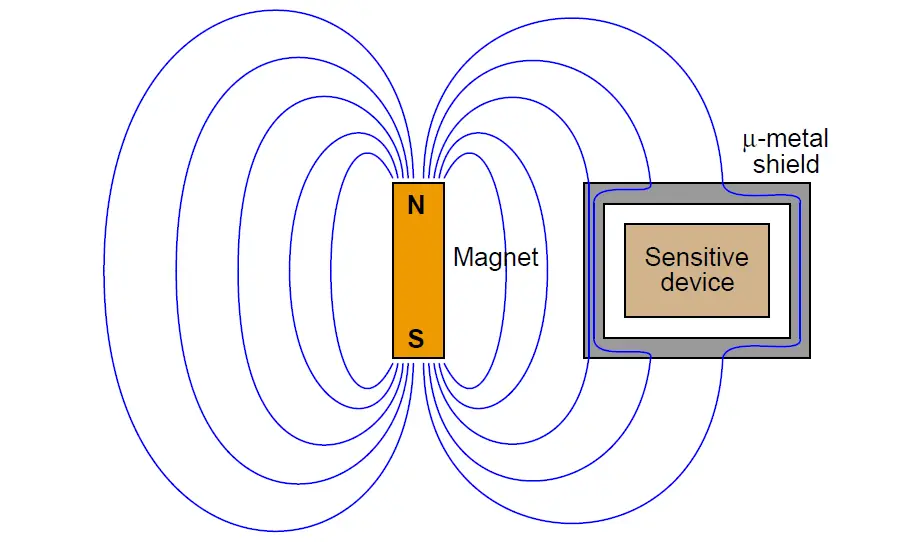
Magnetic fields, unlike electric fields, are exceedingly difficult to completely shield. Magnetic flux lines do not terminate, but rather loop. Thus, one cannot “stop” a magnetic field, only re-direct its path.
A common method for magnetically shielding a sensitive instrument is to encapsulate it in an enclosure made of some material having an extremely high magnetic permeability (μ): a shell offering much easier passage of magnetic flux lines than air.
A material often used for this application is mu-metal, or μ-metal, so named for its excellent magnetic permeability:
Inductive Coupling Effects
This sort of shielding is impractical for protecting signal cables from inductive coupling, as mumetal is rather expensive and must be layered relatively thick in order to provide a sufficiently low-reluctance path to shunt most of the external magnetic flux lines.
The most practical method of granting magnetic field immunity to a signal cable follows the differential signaling method discussed in the electric field de-coupling section, with a twist (literally). If we twist a pair of wires rather than allow them to lie along parallel straight lines, the effects of electromagnetic induction are vastly minimized.
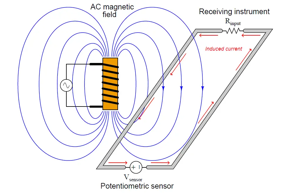
The reason this works is best illustrated by drawing a differential signal circuit with two thick wires, drawn first with no twist at all. Suppose the magnetic field shown here (with three flux lines entering the wire loop) happens to be increasing in strength at the moment in time captured by the illustration:
According to Lenz’s Law, a current will be induced in the wire loop in such a polarity as to oppose the increase in external field strength. In other words, the induced current tries to “fight” the imposed field to maintain zero net change.
According to the right-hand rule of electromagnetism (tracing current in conventional flow notation), the induced current must travel in a counter-clockwise direction as viewed from above the wire loop in order to generate a magnetic field opposing the rise of the external magnetic field.
This induced current works against the DC current produced by the sensor, detracting from the signal received at the instrument.
When the external magnetic field strength diminishes, then builds in the opposite direction, the induced current will reverse. Thus, as the AC magnetic field oscillates, the induced current will also oscillate in the circuit, causing AC “noise” voltage to appear at the measuring instrument. This is precisely the effect we wish to mitigate.
Immediately we see a remarkable difference between noise voltage induced by a magnetic field versus noise voltage induced by an electric field: whereas capacitively-coupled noise was always common-mode, here we see inductively-coupled noise as differential
(This is not to say magnetic fields cannot induce common-mode noise voltage: on the contrary, magnetic fields are capable of inducing voltage in any electrically-conductive loop. For this reason, both differential and ground-referenced signals are susceptible to interference by magnetic fields).
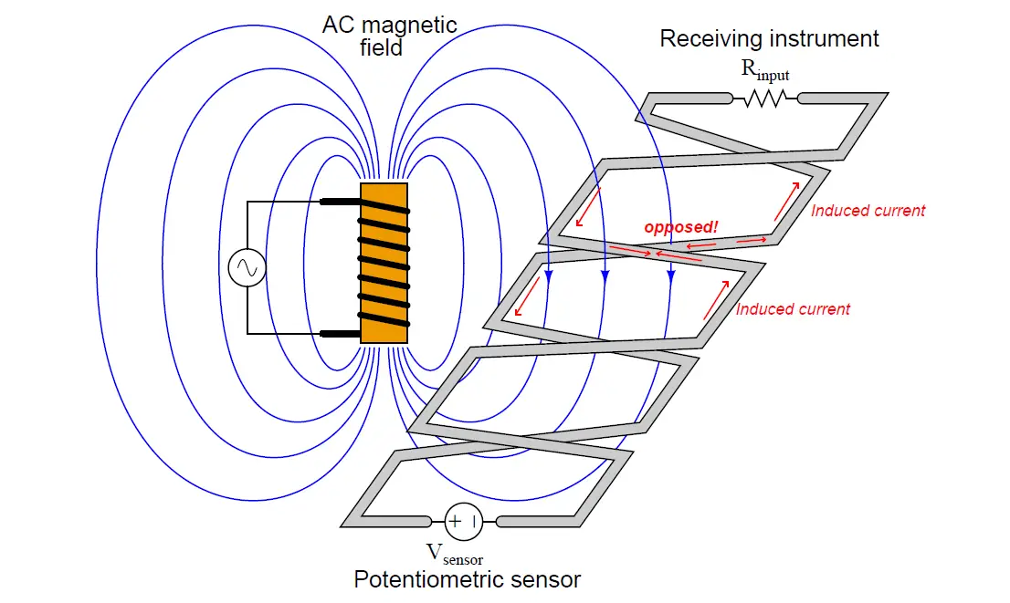
If we twist the wires so as to create a series of loops instead of one large loop, we will see that the inductive effects of the external magnetic field tend to cancel:
Not all the lines of flux go through the same loop. Each loop represents a reversal of direction for current in the instrument signal circuit, and so the direction of magnetically-induced current in one loop directly opposes the direction of magnetically-induced current in the next.
So long as the loops are sufficient in number and spaced close together, the net effect will be complete and total opposition between all induced currents, with the result of no net induced current and therefore no AC “noise” voltage appearing at the instrument.
In order to enjoy the benefits of magnetic and electric field rejection, instrument cables are generally manufactured as twisted, shielded pairs. The twists guard against magnetic (inductive) interference, while the grounded shield guards against electric (capacitive) interference.
If multiple wire pairs are twisted within the same cable, the twist rates of each pair may be made different so as to avoid magnetic coupling from pair to pair (An example of this is the UTP (Unshielded, Twisted Pair) cabling used for Ethernet digital networks, where four pairs of wires having different twist rates are enclosed within the same cable sheath.).






Super knowledge site sir