Hydrostatic tank gauging (HTG) has historically been a cheap means of level measurement that can be used in the fuel storage industry. This method has no wetted or moving parts within the tank.
In addition, with modern versions, because they measure based upon volume to provide a quantity in terms of mass, accurate level measurement is possible. This, in turn, provides a good means of leak detection.
Current versions of this technology also allow the density of material measurement. This component is used in calculating the liquid mass, but a secondary benefit is that it allows the observation of material composition for quality control.
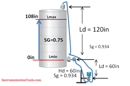
This is a continuous measurement method and works by measuring the pressure at two sensors which are a known distance apart in the tank. The temperature between the two pressure measurement points is also measured.
The accuracy of the measurement that can be achieved with a correctly installed system is up to ±10 mm of the level of the tank. This is generally considered to be because of limitations induced by the pressure sensors used. Therefore, it is considered that HTG systems are a good method of providing a rough indication of tank level, but not sufficient for custody transfer measurement.
It is strongly recommended that if HTG is used in level measurement or overfill protection, it should be accompanied by further secondary high-level alarms. It should be noted that some system designers believe that accuracy comparable to radar and servo gauge systems can be achieved but at a high financial cost, which is a lot of cases would be higher than the cost of radar or servo level measurement systems.
Hydrostatic Tank Gauging
")
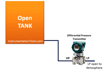
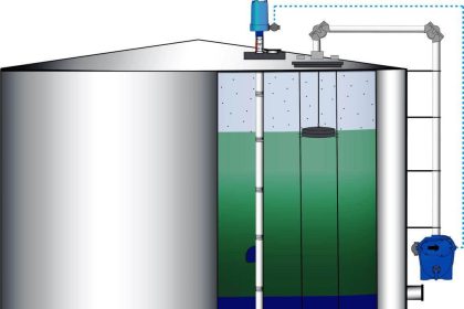
Figure: Simple diagram to demonstrate an HTG level measurement system
The pressure readings are used to calculate the mass of material in the tank using the following series of simplified equations:

This type of level measurement system can be used in stored fuel measurement. However, it is not a favored level measurement system primarily due to the difficulty in maintaining measurement accuracy due to variation of temperature and changing the state of the stored gasoline (fuel).
The non-invasive nature of this system (that is, it has no moving parts) can be implemented using commercially available components and technology. This would make this an attractive level measurement approach if the issue of consistent measurement accuracy was addressed.
Disadvantages of Hydrostatic Tank Gauging
There are a number of limitations associated with HTG systems that are used for level measurement. The accuracy of measurement using this type of system can be reduced if the sensors used become coated or poisoned through prolonged exposure to the fuel substance contained within the tank. Routine maintenance and component replacement should, however, minimize this issue.
The incorrect or insufficient installation and commissioning of an HTG system can cause significant errors in measurement. Another cause of error in level measurement is exposure to air of the pressure sensor because this will cause the pressure induced by the air to be measured instead of the pressure of the stored gasoline.
There is also a known issue with the HTG system sensor configuration where any vapor within the tank will directly affect the pressure measured and thus the measurement accuracy.
Early systems were prone to giving incorrect level measurements with variation in ambient temperatures. This was addressed in newer HTG system designs by the inclusion of temperature sensors which allowed for temperature compensation to be made in the measurement.
However, even with these newer systems, there may still be inaccuracies in measurement if there are multiple materials stored in the tank that have a differing temperature or density characteristics, resulting in a layering of stored material in the tank.
Maintenance of HTG systems focuses mainly on the cleaning of the sensors and removal of sediment build-up at the bottom of the tank, which in itself can cause an inaccurate level measurement.
It is the opinion of system designers the authors spoke to that, in reality, it is hard, if not impossible, to test HTG systems fully because the operator often cannot see into the tank to verify what the product level is unless the system is installed so that it is visible from outside of the tank.
Currently, HTG level measurement is not commonly used for gasoline level measurement. However, it has been cited by the instrument engineers’ handbook, Process Measurement, and Analysis 4th Ed as being used in the following applications:
- Clean liquid measurement (atmospheric and pressurized);
- Hard to handle fluid measurement (atmospheric and pressurized);
- Bi-phase material;
- Cryogenic material;
- Boiling material.
Problems with HTG systems are attributable to the sensors used. Placement, maintenance, and replacement of these parts are key to continued measurement accuracy. Incorrect placement of sensors can lead to error introduction, which can, in turn, lead to inaccurate level measurement.
In order to achieve a high accuracy measurement, the pressure sensors used must be at least 20 to 30 times better (higher quality) than those used in standard process control applications. It is implied that the pressure sensors used in this application must be capable of maintaining calibration between maintenance and inspection intervals.
Hydrostatic Tank Compensation (HTC) can be implemented using one pressure difference sensor, which compensates for measurement errors. This can be introduced when using two individual sensors.
Another drawback of the HTG approach to level measurement is that if a measurement is taken where the level of the liquid is below the height of the higher pressure sensor an unreliable level and density measurement can be given.
Therefore the greatest accuracy in using this type of system is only achievable in a limited portion of the tank, namely in and around the vicinity of the pressure sensors.
Experts Feedback
From the experience of systems integrators spoken to, this method is seldom used in the fuel storage industry. This method uses a multi-parameter probe and is seen as being a big advantage that manufacturers are using to push this method. The main advantage of this method is due to the minimal wetted parts involved, and theoretically little or no overhead for maintenance. However, in practice, this is very unlikely to be the case.
It is also, in theory, straightforward to retrofit the system to existing tanks. The equipment can be lowered into existing stilling wells. This has the advantage of being easily accessible for servicing. The system is also versatile enough to be able to use existing entries into a tank. This can, however, cause problems when routine maintenance is performed.
An American level measurement system design company puts forward a very strong case in support of HTG systems. However, this view is not widely shared. Further limitations of this method are introduced because of its dependence upon temperature and product density. Water in the gasoline storage tank can also lead to incorrect level measurement or misinterpretation of tank contents.
References:
- MHT information factsheet for the energy industry. Hydrostatic Tank Gauging
- Enraf B.V. The Art Of Tank Gauging. The Netherlands: Enraf B.V, Delft VW-IN-44 16.650-V4
Read Next:
- Capacitive Tank Gauges
- Level Transmitter Calibration
- Advantages of Level Sensors
- DP Level Measurement
- Level Measurement with Wet leg