When installing a hydrostatic level transmitter on a working process, one must determine the proper lower- and upper-range values (LRV and URV) for the transmitter in order to properly register 0% at the LRV liquid level and 100% at the URV liquid level.
If all fluid densities and physical dimensions are known in advance, this is a simple matter of a few mathematical calculations.
However, sometimes it is difficult to know all the physical dimensions in advance, especially the elevation or suppression.
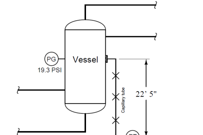
Consider this example, assuming clean water as the process liquid and a static pressure of 0 PSIG inside the (vented) process vessel:
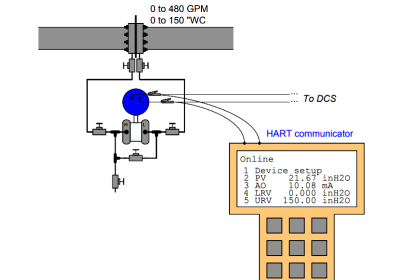
Hydrostatic Level Transmitter

This transmitter has already been calibrated at the instrument shop to accurately register applied pressure, but its range values have not been customized to the installation. Using a tape measure, we find a vertical distance of 38.5 inches between the LRV and URV points marked on the sightglass, and we also see the current liquid level is 17.3 inches above the marked LRV point.
Also Read : Hydrostatic Level Measurement Basics
Using a HART communicator to interrogate this “smart” transmitter, we see that the registered pressure at this process condition is 47.9 inches of water column (”WC), which is greater than 17.3 inches registered by the sightglass due to the transmitter’s suppression (physical location beneath the LRV point, creating a hydrostatic pressure simply due to process water inside the impulse tube).
Based on this information alone, calculate the appropriate LRV and URV settings to program into the smart transmitter, so that it will output 4 mA when the process water level is at the LRV height and 20 mA when the water level is at the URV height:
LRV = _______”WC
URV = _______”WC
Answer :
If the transmitter registers an actual applied pressure of 47.9 ”WC when the process water level is known to be 17.3 inches above the LRV, it means the transmitter must be mounted 30.6 inches below that LRV height:
47.9 ”WC − 17.3 ”WC = 30.6 ”WC
This 30.6 inch suppression then becomes the transmitter’s lower-range value, so that it will output 4 mA (0% signal) when the process water level is at the LRV height and the only pressure sensed by the transmitter is the hydrostatic pressure produced by water inside the 30.6 vertical inches of impulse tube.
The necessary upper-range value is simply this LRV added to the known span of 38.5 inches:
30.6 ”WC + 38.5 ”WC = 69.1 ”WC
so final LRV & URV Values are :
LRV = 30.6 ”WC
URV = 69.1 ”WC
Share your answers and explanation with us through the below comments section.
Read Next:
- Pressure Control Loop
- Which Instrument is Faulty?
- Loop Powered Transmitter
- Instrument Ranging Tips
- Tank Level Transmitter
Credits: Tony R. Kuphaldt


Nice