Inst ToolsInst ToolsInst Tools
  • Courses
  • Automation
    • PLC
    • Control System
    • Safety System
    • Communication
    • Fire & Gas System
  • Instrumentation
    • Design
    • Pressure
    • Temperature
    • Flow
    • Level
    • Vibration
    • Analyzer
    • Control Valve
    • Switch
    • Calibration
    • Erection & Commissioning
  • Interview
    • Instrumentation
    • Electrical
    • Electronics
    • Practical
  • Q&A
    • Instrumentation
    • Control System
    • Electrical
    • Electronics
    • Analog Electronics
    • Digital Electronics
    • Power Electronics
    • Microprocessor
  • Request
Search
  • Books
  • Software
  • Projects
  • Process
  • Tools
  • Basics
  • Formula
  • Power Plant
  • Root Cause Analysis
  • Electrical Basics
  • Animation
  • Standards
  • 4-20 mA Course
  • Siemens PLC Course
Reading: Hydrazine Analyzer Working Principle
Share
Font ResizerAa
Inst ToolsInst Tools
Font ResizerAa
  • Courses
  • Design
  • PLC
  • Interview
  • Control System
Search
  • Courses
  • Automation
    • PLC
    • Control System
    • Safety System
    • Communication
    • Fire & Gas System
  • Instrumentation
    • Design
    • Pressure
    • Temperature
    • Flow
    • Level
    • Vibration
    • Analyzer
    • Control Valve
    • Switch
    • Calibration
    • Erection & Commissioning
  • Interview
    • Instrumentation
    • Electrical
    • Electronics
    • Practical
  • Q&A
    • Instrumentation
    • Control System
    • Electrical
    • Electronics
    • Analog Electronics
    • Digital Electronics
    • Power Electronics
    • Microprocessor
  • Request
Follow US
All rights reserved. Reproduction in whole or in part without written permission is prohibited.
Inst Tools > Blog > Analyzers > Hydrazine Analyzer Working Principle

Hydrazine Analyzer Working Principle

Last updated: October 6, 2017 3:59 am
Editorial Staff
Analyzers
1 Comment
Share
3 Min Read
SHARE

Measuring principle

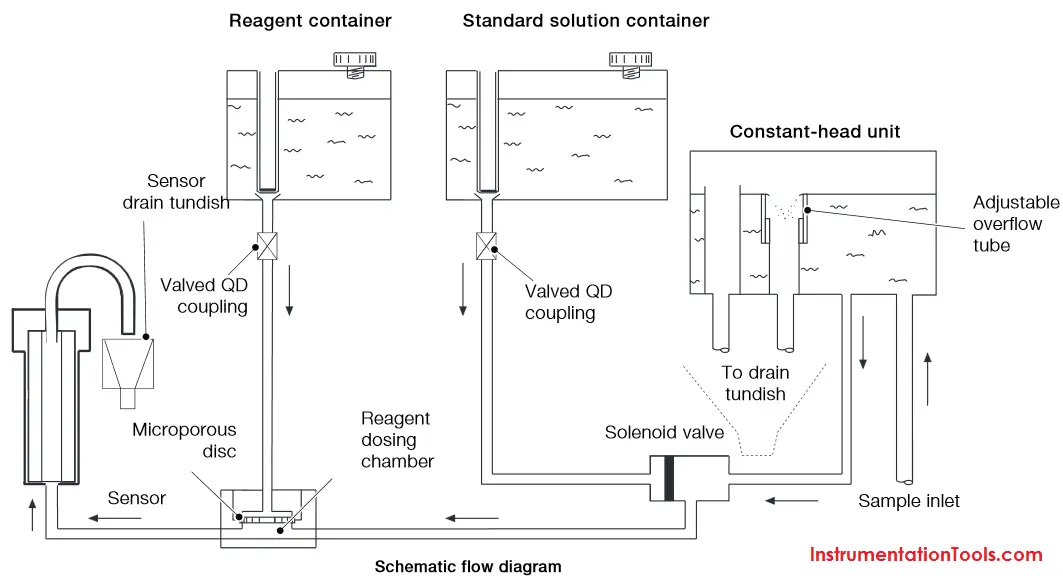
The sample enters the analyzer via the user-adjustable constant-head unit mounted within the enclosure that removes the effect of changes in sample pressure and flow-rate. Overflow from the constant-head unit drains into a tundish at the bottom of the enclosure.

The constant sample flow passes through the calibration valve manifold into the reagent dosing chamber where an alkali reagent is added via a micro-porous disc to raise the pH of the sample to 10.5. The dosed sample passes through a mixing coil before entering the hydrazine sensor.

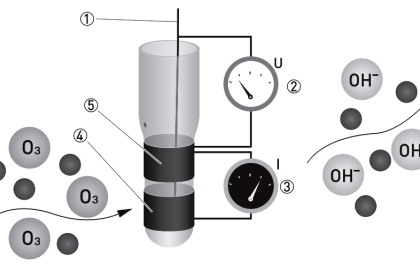
The hydrazine sensor comprises a central ceramic tube inside a gel-filled outer jacket. A silver cathode wire is wound round the outer surface of the tube and a spiral platinum anode is inserted down the center. Sample flows up through the tube, over the platinum anode and out to waste. Electrical contact between the two electrodes is made via the ionic transport through the porous ceramic tube.

The resultant current is proportional to the concentration of hydrazine in solution. The hydrazine sensor and its overflow funnel are mounted on a
sub-panel whose height, relative to the standard solution, can be adjusted to provide the correct rate of flow through the sensor.

A temperature sensor, fitted in the hydrazine sensor flowcell, measures the temperature of the sample. The signal from the hydrazine sensor and the temperature sensor is passed to the smart board Controller. The smart board controller accurately calculates the hydrazine measurement result and transfers it digitally to the display.

Hydrazine analyzer Working Principle

Applications

Typical applications for the hydrazine analyzer include:

— Monitoring and control of hydrazine dosing of boiler feedwater
— Monitoring dosing efficiency prior to economizer inlet

Hydrazine in boiler feedwater

The need for accurate dosing :

To reduce dissolved oxygenlevels, boiler feedwater is commonly dosed with hydrazine before it enters the boiler. Typically, dosing in a ratio of 3 parts hydrazine to the expected level of dissolved oxygen enables operators to achieve an acceptable concentration of below 5μgkg.

Hydrazine also reacts with soft haematite layers on the boiler tubes, forming a hard magnetite layer that protects the tubes from further corrosion.

To ensure that the correct amount of hydrazine is added to the boiler feedwater, measurements must be taken at both the point of dosing and the economizer feedwater inlet. Adding too little hydrazine results in higher levels of dissolved oxygen in the boiler and impairs the formation of magnetite on the boiler tubes, reducing their resistance to corrosion. Adding too much is unnecessarily wasteful and incurs higher chemical treatment costs.

Don't Miss Our Updates
Be the first to get exclusive content straight to your email.
We promise not to spam you. You can unsubscribe at any time.
Invalid email address
You've successfully subscribed !

Continue Reading

Humidity Sensing Absorption Hydrometer Principle
Difference Between Absolute and Relative Humidity
Single-beam Non-dispersive Analyzer
Non-Dispersive Analyzers
Dual-beam Non-dispersive Analyzer
Sodium Analyzer Problems and Troubleshooting Steps
Share This Article
Facebook Whatsapp Whatsapp LinkedIn Copy Link
Share
1 Comment
  • chrish says:
    September 24, 2016 at 10:20 am

    This words are very useful in my study field

    Reply

Leave a Reply Cancel reply

Your email address will not be published. Required fields are marked *

Stay Connected

128.3kFollowersLike
69.1kFollowersFollow
210kSubscribersSubscribe
38kFollowersFollow

Categories

Explore More

Mass Spectrometer Working Principle
Conductivity Analyzers Interview Questions & Answers
Tunable Diode Laser Analyzer Working Principle
Absorption Type Optical Analyzer
Thermal Conductivity Detector (TCD) Principle
NDIR Gas Analyser Working Principle
Pulsed Fluorescence SO2, H2S, CS Analyzer Working Principle
Oxygen Analyzer Working Principle

Keep Learning

process chemical analyzer calibration

Automated Calibration

Turbidity Sensor Calibration Procedure

Turbidity Sensor Calibration Procedure

what-is-gas-metering-system

What is Gas Metering System?

Technologies for Oxygen Gas Measurement

Technologies for Oxygen Gas Measurement

Flame Ionization Detector (FID)

Flame Ionization Detector (FID) Principle

Falling Ball Viscometer Principle

Falling Ball Viscometer Principle

How to Calibrate pH Electrode?

How to Calibrate pH Electrode?

Ozone analyzer principle

Ozone Analyzer Working Principle

Learn More

Radar Level Transmitter in Briddle level Measurement

Radar Level Transmitter in Briddle level Measurement

Electronic Devices & Circuits Objective Questions

Electronic Devices & Circuits Quiz – Set 3

Temperature Transmitter with Thermocouple

Thermocouple Extension and Compensating Cables

RTD Standards list

RTD Standards

What is Wellhead Control Panel?

process chemical analyzer calibration

Automated Calibration

Allen Bradley PLC Example with Sub routines

How to use Sub Routines with Allen Bradley PLC

Online Simulation

Menu

  • About
  • Privacy Policy
  • Copyright

Quick Links

  • Learn PLC
  • Helping Hand
  • Part Time Job

YouTube Subscribe

Follow US
All rights reserved. Reproduction in whole or in part without written permission is prohibited.
Welcome Back!

Sign in to your account

Username or Email Address
Password

Lost your password?