This book is a general guide to the specification, design, and installation of automated industrial control systems.
Industrial Control System Book
This Control system book consists of 7 chapters as mentioned in the below table.
| Chapter 1 | Consider Safety First |
| Chapter 2 | Identifying Processes for Automation |
| Chapter 3 | Specify Devices |
| Chapter 4 | Design |
| Chapter 5 | Build |
| Chapter 6 | Install and Start-up |
| Chapter 7 | Maintain |
All control systems can typically be defined as having inputs, outputs, and some form of decision-making going on in between so that the outputs are controlled based on the status of the inputs.
This device is the “decision-making” element. This element can be performed by a PLC, where we have inputs, outputs, and a central processing unit (CPU) that uses ladder logic programming to make decisions based on input status and the logical conditions in the program.
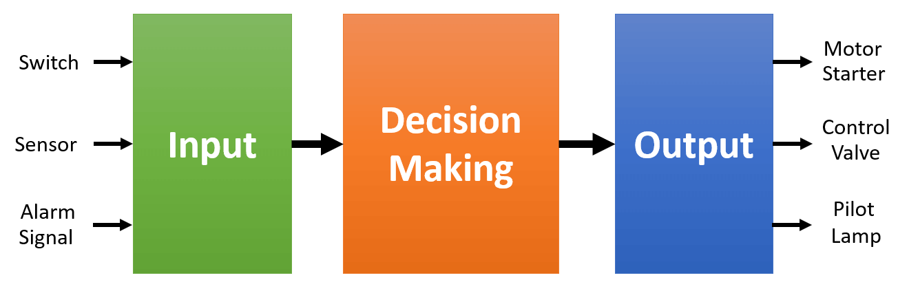
Discrete Input Devices
Discrete input devices are used to sense a condition, detect movement or position, indicate a limit or set point has been reached, sense intervention by an operator, detect an alarm, etc.
Typical input devices may include limit switches, photosensors, pushbuttons, proximity sensors, etc. These input signals are generally in an ON or OFF state.
We can look at input from a device, such as a photosensor used to detect an obstruction, and state that when the photosensor sees the obstruction the sensor is ON; in other words, we have a true condition.
When the photosensor is not obstructed, then the input is OFF; or we can say the condition is false. These types of signals are called discrete signals, meaning they are always in one of two states; ON or OFF.
They can be wired into a PLC input module and the PLC can be programmed to use the status of the signals to execute the logic to control the automated system. Or these same signals can be used in a “relay logic” system, where control relays are hardwired as the logic.
Discrete Output Devices
Discrete output devices are used to control actions such as motion, start/stop of equipment like conveyors and pumps, on/off control of valves, operator alerts/prompts, status indications, etc.
Typical output devices include relays, motor starters, and pilot lights etc. These types of output signals are also discrete; either ON or OFF.
The signals can be wired from a PLC output module to control the devices, such as starting and stopping motors, energizing a valve to control water flow, illuminating a pilot light to alert an operator to a condition such as “Bin Full”, etc.
The output signals can also be wired directly to the controlling device based on hardwired relay logic.
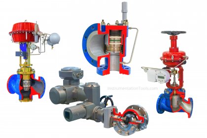
Analog Devices
Another area of inputs and outputs involves the use of analog signals in a control system. Analog signals are variable and can represent a range of values.
As a quick example, we may want to monitor the level of a liquid in a tank that is 100 feet tall.
We can use a sensor that will produce a signal that is represented by a voltage range of 0 to 10 volts DC, with 0 feet being equal to 0VDC and 100 feet being equal to 10VDC.
Analog signals are typically linear, so a 5VDC signal would tell us the tank level is at 50 feet.
The analog signal could be wired into a PLC analog input module, and in the ladder program, we could compare the actual level to a setpoint and produce a discrete signal that would cause an output point to start a pump to raise or lower the level.
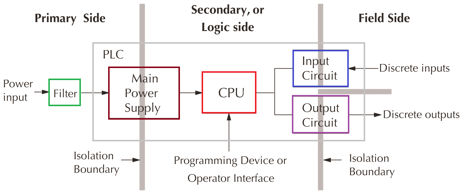
PLC
PLCs provide ideal isolation because its circuitry is divided into three main regions separated by isolation boundaries as shown below.
The PLC’s main power supply includes a transformer that provides isolation, and the input and output circuits that use opto-couplers to provide additional isolation.
When wiring a PLC, it is extremely important to avoid making external connections that connect logic side circuits to any other.
Maintenance Checklist
The below list shows the brief checklists to be performed periodically on the machines and equipment.
- Check and record voltages at various circuits
- Tighten all connections (with power removed)
- Check backup batteries, and/or replace on a routine schedule
- Check indicators and perform lamp tests
- Visually inspect for loose or frayed wiring, moisture in enclosure, etc.
- Check to make sure plug-in connectors are tight and secured
- Test all alarm systems, horns, sirens, etc.
- Check and record any configuration settings
- Perform and record calibrations
- Check all I/O points on a yearly basis
- Check and record power usage
- Check equipment run times for determining maintenance or replacement
- Measure device current to set a benchmark and compare for changes
- Review any diagnostic history, including events and alarms
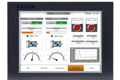
- Check diagnostics that may be programmed into the HMI operator interface.
| Title: | An Industry Guide to Control System Engineering |
| Author: | Automation Direct |
| Format: | |
| Size: | 4.5 MB |
| Pages: | 93 |
| Download: | Click Here |
Also See: Instrumentation Books


Thanks