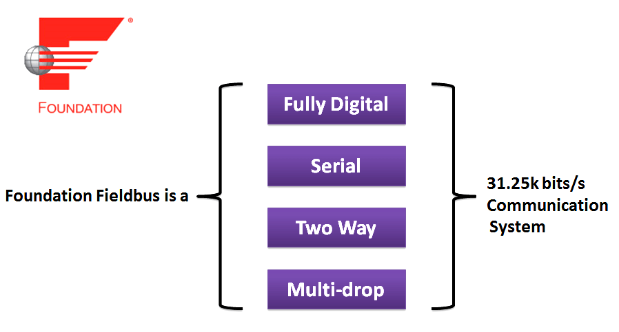
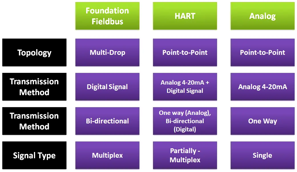
Foundation™ Fieldbus is a fully digital, serial, two-way, multi-drop communication system running at 31.25 Kbits/s which is used to connect intelligent field equipment such as sensors, actuators, and controllers.
Foundation™ Fieldbus allows “multiple variables” from each device to be brought into the control system for archiving, trend analysis, process optimization, reporting, predictive maintenance, and asset management.
Foundation Fieldbus
It serves as a Local Area Network (LAN) for the instrumentation used within process plants and facilities with built-in capability to monitor and distribute control applications across the network.
In Fieldbus multiple process variables, as well as other information can be transmitted along a single wire pair. Self-diagnostics and communication capabilities of microprocessor based fieldbus devices helps reduce downtime and improve plant safety.
Many control system functions such as AI, PID and AO can be performed by the field device through the use of these Standard Function Blocks. Distribution of control into field devices can reduced the amount of hardware needed.
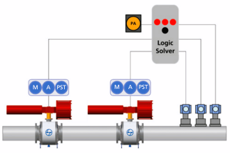
Multi-drop connection is to connect multiple field devices to a single cable, and the reduction of cables brings a lot of advantages. Here is an example of a multi-drop connection as shown below:

In an analog transmission system, only one field device can be connected to a single cable that leads to a system. The multi-drop connection allows multiple field devices to be connected to a single cable. Where there is a cable already laid, additional field devices can be connected later.
In the past, the multi-drop connection of field devices was costly. With introduction of the multidrop connection of the fieldbus communication system, more field devices can be connected to a single fieldbus without increasing the wiring cost.
Fieldbus is quite different from the traditional approach of connecting 4 – 20mA devices to a DCS system using dedicated pairs of wires for each device. Field devices and segment becomes a part of DCS.
This shall require an integrated approach of configuration, data management and system architecture approach to field network design. Complex functions can be achieved within the FF devices, which lead to significant cost saving and appreciably reduces the commissioning and start-up time.
Foundation Fieldbus is utilized for majority of the process control applications, including the field instruments connected to the DCS. This includes Control Valves, Motor Operated Valves, Transmitters and Local Indicators.
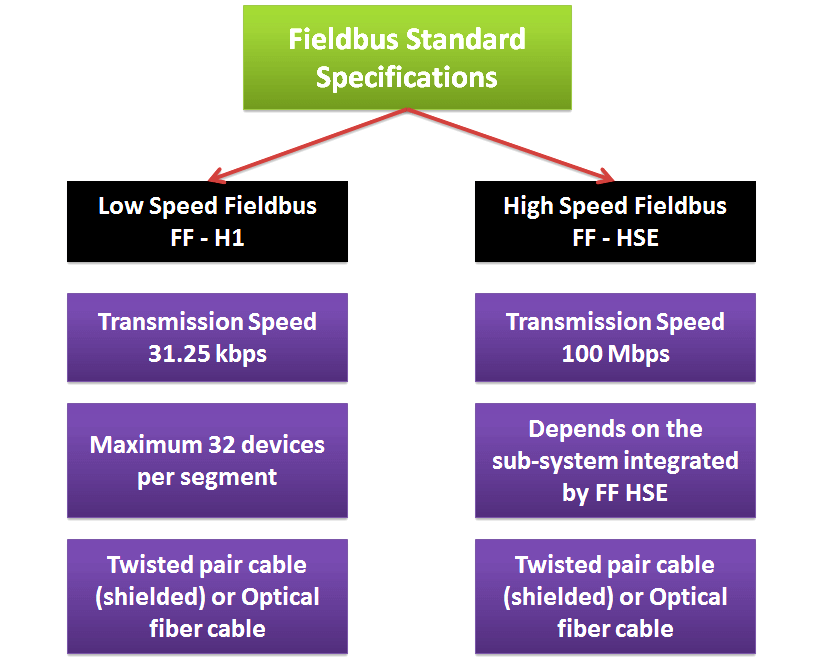
Fieldbus Standard Specifications
There are low-speed and high-speed fieldbus physical layer specifications standardized by IEC61158-2 and ISA S50.02.
The high-speed fieldbus specification was not adopted for development and High Speed Ethernet (HSE) specification was added as an additional type.
Multivariable means multiple measured variables. Multivariable detection, or multiple sensing, means detecting multiple measured variables by a single field device.
Analog versus Fieldbus
A conventional analog transmission system requires one cable for each measured variable; however, the fieldbus supports multivariable transmission. It means a field device can transmit all the detected measured variables via a single cable.
The differences in wiring of a control valve between analog and fieldbus communication systems are as shown below:
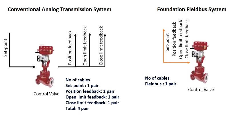
In the conventional analog transmission system, a control valve transmitted only the control output signal to the positioner.
In the fieldbus communication system, multiple pieces of information such as control signals, limit signals, and valve position signals can be detected and transmitted.
More information can also be utilized for expanding control and measurement capabilities.
Advantages of Foundation Fieldbus
- Reduced number of wires and marshaling panels,intrinsic safety barriers, Input/Output cards, power supplies,
- Reduced size of equipment Rooms,
- Remote and diagnostic configuration of devices,
- More information available for operations and maintenance,
- Increased accuracy of measurements,
- Increased up-time and reduced commissioning time,
- Better self diagnostics and remote diagnostics.
Limitations of Foundation Fieldbus
Foundation Fieldbus is not utilized for applications requiring extremely fast control system response (200mS or below), such as Anti-Surge control, or for applications requiring high signal bandwidth, such as Machine Condition Monitoring systems.
Foundation Fieldbus Architecture
H1 is a term used to describe a FOUNDATION fieldbus network operating at 31.25 kbit/second.
A Segment is a section of a FOUNDATION fieldbus H1 fieldbus terminated in its characteristic impedance. Segments can be linked by Repeaters to form a longer H1 fieldbus. Each segment can include up to 32 H1 devices.
The term “segment” is used to represent a cable and devices installed between a pair of terminators. The FOUNDATION fieldbus specifications use the term “network” to describe the system of devices. It has become industry practice to use the two terms interchangeably.
A fully loaded (maximum number of connected devices) 31.25 kbit/s voltage-mode fieldbus segment shall have a total cable length, including spurs, between any two devices, of up to 1,900 m.
The maximum number of devices on any segment (including future devices) shall be no greater than 12. Minimum spare capacity should be defined as 20 %.
Therefore, if the maximum number of field devices per segment for a project is 12, taking into account spare capacity for future expansion, the maximum number of devices to be installed into a segment shall be 10 at the start of the project.
This also takes care of future addition of one control loop (e.g.: one transmitter and one final element). Therefore, each segment shall be designed for a minimum of two future devices.
For 20 % spare additional current capacity shall be considered for future expansion.
Most Foundation Fieldbus devices can be powered directly from the Fieldbus. The DC supply voltage can range for 9 -32 Vdc.
The transmitting device delivers ± 10mA at 31.25kbits/s into a 50 ohm equivalent load to create a 1.0 volt peak-to-peak voltage modulated on top of the direct current (DC) supply voltage.
Topologies
There are several possible Foundation Fieldbus topologies.
Tree topology is detailed in diagram below:
The Foundation Fieldbus shall be implemented utilizing 5-pair trunk cables from marshalling cabinets to intermediate junction boxes located within the various plant areas.
This method shall reduce the number of Foundation Fieldbus cables entering the Panel Building with associated cost saving. All multi-pair trunk cables shall contain only Foundation Fieldbus signals.
Typically each segment from the Intermediate Junction Box shall utilize multi pair cable for the trunk (H1) to the Foundation Fieldbus Junction Boxes.
The multi-pair cable runs between the Intermediate FF J-Box and marshalling cabinets. A single pair cable run between the Intermediate FF J-Box and the FF Spur J-Box
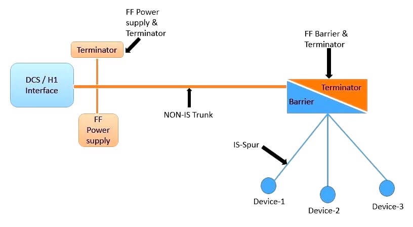
The Foundation Fieldbus Spur Junction Boxes are of a split design with the high power trunk (non-IS) on one side and on the other side the FF barriers and associated surge protection and/or terminals (IS) for Hazardous Area.
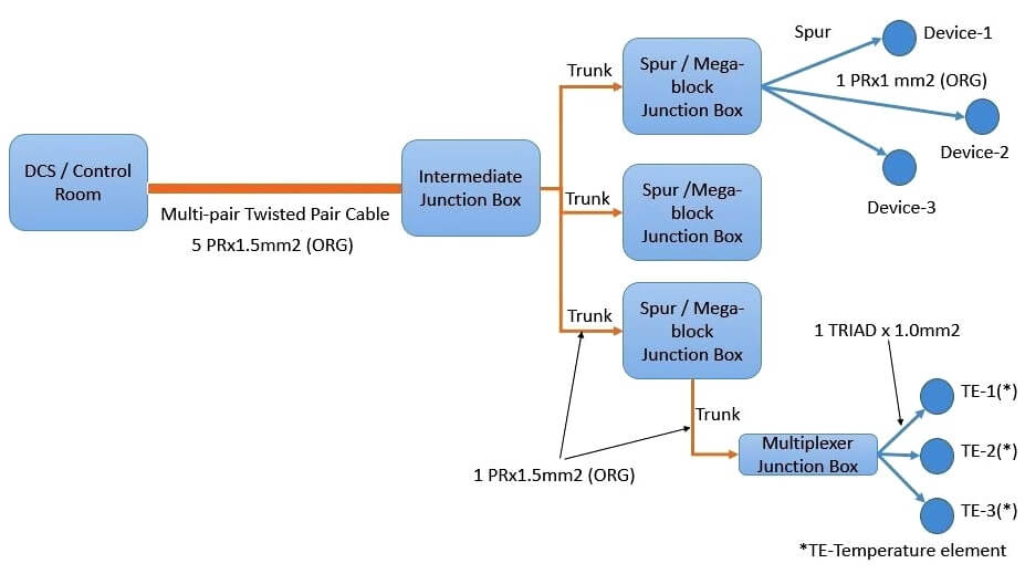
For the Non-Hazardous area, FF barriers and above JB configuration are not required. For the Non-Hazardous area, a wiring hub like Mega Block shall be used Depending if the zone is Non-IS then megablock junction box is used instead of the Spur junction box (used in IS zone).
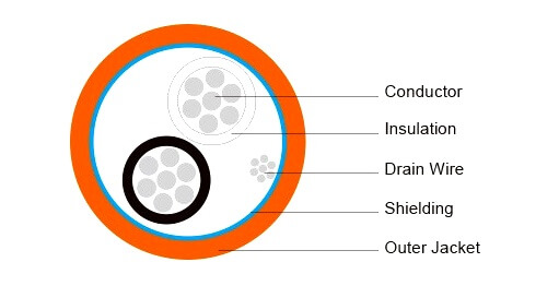
All H1 Spur cables shall be “Type A”, as specified in IEC-61158-2, i.e. single twisted pair with an overall shield. It will also comply to FF-844 (H1 cable test specification).
All H1 Trunk cables shall be multiple twisted-pair, with individual and overall shields. All H1 Trunk cables shall meet the electrical parameters for “Type A” cables specified in IEC-61158-2.
The maximum allowable total cable (trunk plus all spurs) length of a Foundation Fieldbus segment shall not exceed 1900 meters. The maximum allowable trunk length according to FF rules is 1200m. The maximum allowable spur length according to field barrier design is 120m.
All H1 Spur cable shall be 1 mm2 IS. Single pair cable to field instruments. Two pair 1 mm2 IS to Temperature Multiplexer JBs (as it contains two mux devices) H1 Trunk cable shall be by default 1.5 mm2 Non-IS for trunk lengths of upto 1000m.
In case of projects were large number of temperature elements is not envisage they can opt for single multiplexer in such case one pair 1mm2 IS is sufficient.
Earthing Scheme
Fieldbus system is highly susceptible to electrical noise that may be induced by electromagnetic/electrostatic induction, from radio wave and/or ground potential differences, etc.
The proper signal grounding design and construction methods shall be provided in order to prevent influence from any electrical noise. This will help to maintain required Fieldbus communication signal quality on a H1 segment.
All Fieldbus signal cores are preserved differentially throughout the network, as grounding either conductor would cause all Fieldbus devices on that H1 segment to lose communications for the period that the conductor is grounded.
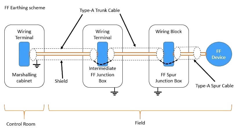
The instrument shields of multi pair trunk cable are terminated and grounded at the DCS end of the H1 segment in the marshalling cabinet and are not connected to ground at any other place.
The instrument shield of single pair trunk cables are connected to instrument shield of multi-pair trunk cable at the Intermediate Foundation Fieldbus Junction Box.
The Spur cable shields are connected to the trunk cable shield at the wiring block inside the FF Spur JB and left unconnected at the Fieldbus device. Shield should be covered by heat shrink/sleeve to avoid any possibility of inadvertent grounding.
Above Heat shrink over the inner sheath of the Multipair cable. No connection shall be made between the trunk or spur cable shields and the Fieldbus junction box. Safety (case) ground of FF devices, Intermediate FF Junction Boxes and FF Spur Junction Boxes are made at each component.
Fieldbus cable shields from different networks segments shall not be connected. Spare pair from Intermediate Junction box to marshalling cabinet shall be terminated in spare TB’s and are further connected to panel instrument shield bus bar.
Terminators shall be provided at both ends of a FF segment. The field terminator shall be installed in the FF Spur junction box at the farthest end of the trunk.
No terminators shall be installed in the FF device.The terminator at the DCS side shall be incorporated into the FFPS and enabled utilizing a jumper or dip switch.
All Trunks will have surge protection at both ends i.e. in the marshalling cabinet and the FF spur junction box. Surge protection for each instrument shall be considered in areas with a high susceptibility to lightning strikes these areas include, tank farms, etc. and any areas where instrumentation is not significantly shielded by the plant steel work and pipe racks.
This is realized through the use of surge protectors installed on each susceptible field devices. Surge protectors are earthed to the local protective earth.
All field instruments having electrical or electronic connections shall be suitable for installation in the defined hazardous area. Minimum equipment certificate shall be as per project requirement. All Foundation Fieldbus devices shall be certified Intrinsically Safe FISCO.
The method of I.S. protection employed for the projects will be a high power trunk ‘Hybrid’ concept. This method uses the Increased Safety (Ex e) concept of protection for the Fieldbus Trunk and has the benefit of delivering a higher level of current to the Fieldbus segment than is possible with Intrinsic Safety.
Intrinsically safe spurs are generated by using a field mounted Fieldbus Barrier to limit the power, voltage and current available to the field device. This type of implementation allows full access to the field devices when they are energized inside the hazardous area.
This solution shall be realized through the use of enclosures which provide a bus powered Fieldbus Barrier with no requirement for an external power source; through the use of special ‘Live-Disconnect’ terminals making Fieldbus Barriers, replaceable whilst energized in a hazardous area.
The spurs are galvanically isolated from the trunk and from each other, have spur short circuit protection, and shall not require protective earth to be provided in the field.
For the Non-Hazardous area, FF barriers and split JB configuration is not required. For the Non-Hazardous area wiring hub like Mega Block shall be used. The wiring hub shall provide individual device (Spur) isolation and fault in one device shall not affect segment.
Read Next: