Inst ToolsInst ToolsInst Tools
  • Courses
  • Automation
    • PLC
    • Control System
    • Safety System
    • Communication
    • Fire & Gas System
  • Instrumentation
    • Design
    • Pressure
    • Temperature
    • Flow
    • Level
    • Vibration
    • Analyzer
    • Control Valve
    • Switch
    • Calibration
    • Erection & Commissioning
  • Interview
    • Instrumentation
    • Electrical
    • Electronics
    • Practical
  • Q&A
    • Instrumentation
    • Control System
    • Electrical
    • Electronics
    • Analog Electronics
    • Digital Electronics
    • Power Electronics
    • Microprocessor
  • Request
Search
  • Books
  • Software
  • Projects
  • Process
  • Tools
  • Basics
  • Formula
  • Power Plant
  • Root Cause Analysis
  • Electrical Basics
  • Animation
  • Standards
  • 4-20 mA Course
  • Siemens PLC Course
Reading: Example of Feedback System
Share
Font ResizerAa
Inst ToolsInst Tools
Font ResizerAa
  • Courses
  • Design
  • PLC
  • Interview
  • Control System
Search
  • Courses
  • Automation
    • PLC
    • Control System
    • Safety System
    • Communication
    • Fire & Gas System
  • Instrumentation
    • Design
    • Pressure
    • Temperature
    • Flow
    • Level
    • Vibration
    • Analyzer
    • Control Valve
    • Switch
    • Calibration
    • Erection & Commissioning
  • Interview
    • Instrumentation
    • Electrical
    • Electronics
    • Practical
  • Q&A
    • Instrumentation
    • Control System
    • Electrical
    • Electronics
    • Analog Electronics
    • Digital Electronics
    • Power Electronics
    • Microprocessor
  • Request
Follow US
All rights reserved. Reproduction in whole or in part without written permission is prohibited.
Inst Tools > Blog > Control Systems > Example of Feedback System

Example of Feedback System

Last updated: July 13, 2019 12:52 pm
Editorial Staff
Control Systems
No Comments
Share
3 Min Read
SHARE

Home furnace control system must control the temperature in the room and kept it constant.

As in open loop system a timer is used to switch on the furnace for some time and then switch it off, accuracy is not obtained.

This is because the system does not act according to the room temperature but according to a preset value of time.

Example of feedback principle

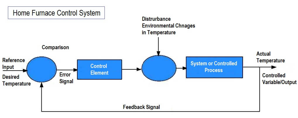
A closed loop control system takes care of this problem. The feedback unit (the main component of the closed loop control system) senses the room temperature and accordingly turns on or off the furnace.

The feedback unit feeds the output back to a comparator which is provided with a reference value with which the output is compared to generate an error signal. This error signal generates the required control action.

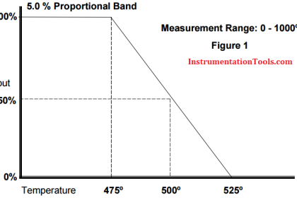
In the home furnace control system, a temperature sensor is used to sense the temperature in the room and this is feedback to an error detecting device. The error detecting device compares the room temperature with the reference value.

If it detects that the room temperature is higher than the reference value, if generates a signal to switch off the furnace. On the other hand, if it detects that the room temperature is lower than the reference value, it generates a signal to switch on the furnace. This has been shown in the figure.

Hence it is clear that a system with feedback (closed loop control system) is efficient than that of a system without feedback (open loop control system).

Human Control System

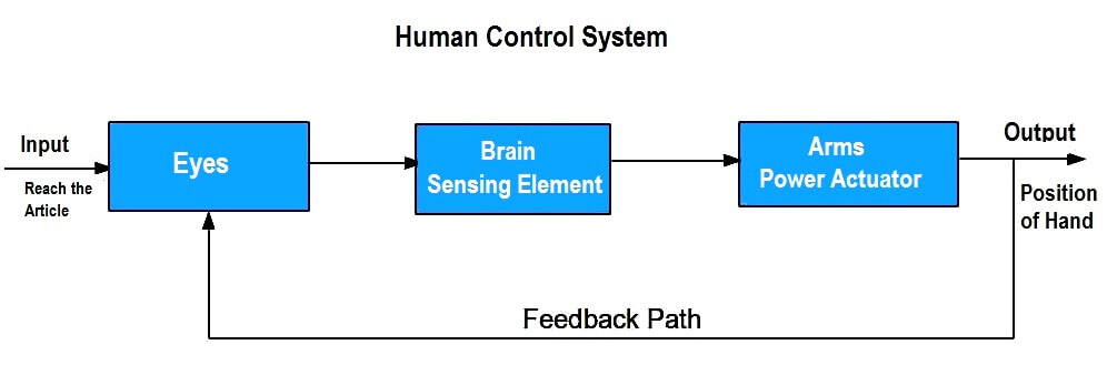
Another examples of a closed loop control system is the working of a human brain. If a person wants to pick up an article say bag or book, the brain instructs the hand to reach the article and the eyes constantly keep giving the feedback to the brain regrading the posistion of the hand relative to the article.

But if the person is asked to reach the article closing his eyes, he can reach it only approximately. Thus the human system is a very accurate feedback control system. The control system taking human as an example is shown in the figure.

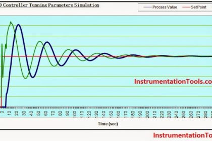
While designing a closed loop system, a compromise between stability and accuracy is to be established. This is because the gain of the system may exceed over a limit which may cause the system to be over correct, leading the system to become unstable, that is, oscillation of the output without bound.

Note

Gain is the ratio between the amplitude of the output to the amplitude of input. The variation of the gain over a range of the frequencies is called frequency response. Moreover, due to mechanical problems like friction, the system might tend to have a steady state error.

Don't Miss Our Updates
Be the first to get exclusive content straight to your email.
We promise not to spam you. You can unsubscribe at any time.
Invalid email address
You've successfully subscribed !

Continue Reading

How to Write a Program in Ecostruxure Machine Expert HVAC Software?
Network Cabling
Instrumentation Engineer Activities & Documents – Detail Design Phase
Most Asked Questions on SCADA with Answers
Feedforward Control with Dynamic Compensation
Difference between Availability, Reliability & SIL
Share This Article
Facebook Whatsapp Whatsapp LinkedIn Copy Link
Share
Leave a Comment

Leave a Reply Cancel reply

Your email address will not be published. Required fields are marked *

Stay Connected

128.3kFollowersLike
69.1kFollowersFollow
210kSubscribersSubscribe
38kFollowersFollow

Categories

Explore More

Determining the Design Purpose of Override Controls
Difference Between Single Pair Ethernet and Traditional Ethernet
How to Export Data from DeltaV System to Excel
Selection of Components Used In Electrical Earthing or Grounding
What is a Signal Isolator? Principle, Advantages, Disadvantages
What is Electromagnetic Noise Interference?
Electrical Earthing Calculations
Node-RED in PLC Industrial Automation

Keep Learning

Selector Control Function in DCS

Selector Control Functions

Fixed Type Motor control center (MCC)

Motor Control Center (MCC) Signal Interface Termination (SIT)

Basics of Trips, Interlocks, Permissives & Sequences

Basics of Trips, Interlocks, Permissives & Sequences

Create a Project in LabVIEW

How to Create a Project in LabVIEW?

On-Off Controller example

ON-OFF Controller Principle

control of temperature in a vessel

How to Analyze PID Controller Actions

Difference Between SCADA and HMI

Difference Between SCADA and HMI

Hardwired IO and Serial IO - Differences Explained

Hardwired I/O and Serial I/O – Differences Explained

Learn More

Landline Telemetry Objective Questions

Landline Telemetry Objective Questions

Open Circuit without Freewheeling diode

Freewheeling Diode Working Principle

PLC TB Wiring

Electrical Signal and Control Wiring

Proportional Controller Response Curve

Proportional Controller Principle

Step and Touch Potential

What Is Step and Touch Potential and Reducing Resistance To Ground?

Questions and Answers on Valves

Valve Quiz

Closed Tank Non-Zero-Based Direct Mount Application

Open and Closed Tank Level Calculations

Weigh Feeder Drive

Failing Weigh Feeders and Mechanical Variable Speed Drives (VSD)

Menu

  • About
  • Privacy Policy
  • Copyright

Quick Links

  • Learn PLC
  • Helping Hand
  • Part Time Job

YouTube Subscribe

Follow US
All rights reserved. Reproduction in whole or in part without written permission is prohibited.
Welcome Back!

Sign in to your account

Username or Email Address
Password

Lost your password?