This article will discuss an automatic speed control system for escalators based on passenger load using the PLC with XG5000 software. The system aims to automatically regulate the movement of the escalator based on the number of users present. It features multiple speed levels that decrease as the number of escalator users increases, allowing for energy savings by activating the escalator only when needed. The PLC system is equipped with an emergency stop feature to enhance user safety.
Program Objective
System Steps:
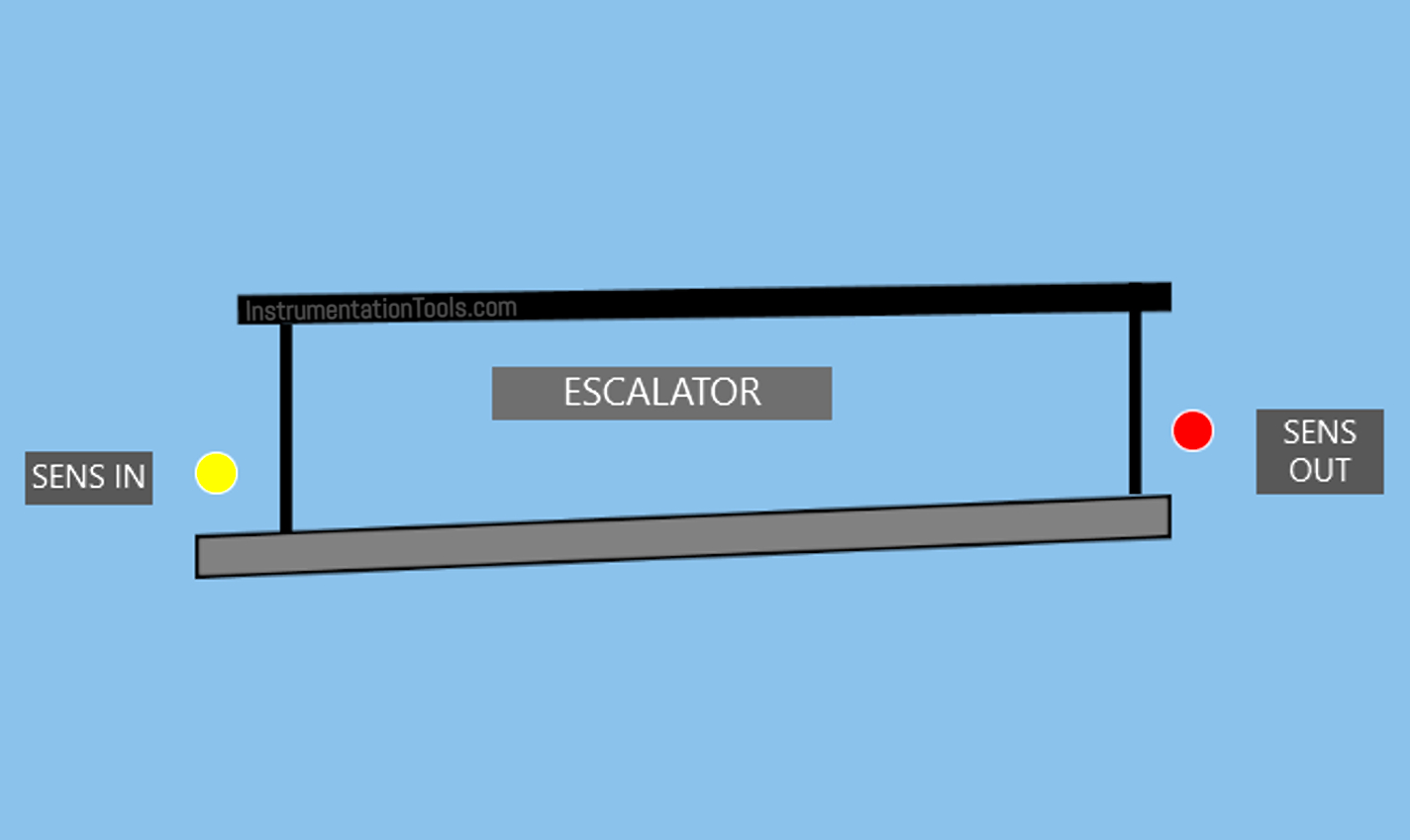
User Detection:
- A PIR sensor is used to detect the presence of people approaching the escalator.
- If no one is detected, the escalator will stop to save energy.
- If people are detected, the system will reactivate the escalator motor.
Escalator Activation
- The speed of the escalator will decrease as the number of passing individuals increases, for safety purposes.
The escalator has 3 speed levels:
- When no one is detected, the escalator will stop.
- When 1-4 people are detected, the escalator will operate at a speed of 10 km/h.
- When 4-8 people are detected, the escalator will operate at a speed of 6 km/h.
- When 8-12 people are detected, the escalator will operate at a speed of 4 km/h.
Automatic Shutdown:
- If the sensor does not detect any presence of people, the system will stop the motor to save energy.
- If another user is detected, the system will run again automatically.
Safety Features:
- An Emergency Stop Button is used to halt the escalator during emergencies.
- A Fault Alarm will activate when the Emergency Button is Pressed.
Escalator Control Based on Passenger Load
IO Mapping
| S.No. | Comment | Input (I) | Output (Q) | Memory Words | Memory Bit |
|---|---|---|---|---|---|
| 1 | PB_START | P0000 | |||
| 2 | PB_STOP | P0001 | |||
| 3 | SENS_IN | P0002 | |||
| 4 | SENS_OUT | P0003 | |||
| 5 | EMERGENCY | P0004 | |||
| 6 | MOTOR | P0040 | |||
| 7 | LAMP_EMERGENCY | P0041 | |||
| 8 | TEMP_PEOPLE | M000 | |||
| 9 | SPEED_MOTOR | M001 | |||
| 10 | SYSTEM_ON | M1000 | |||
| 11 | IR_MOTOR1 | M1001 | |||
| 12 | IR_MOTOR2 | M1002 | |||
| 13 | IR_MOTOR3 | M1003 |
PLC Program Explained
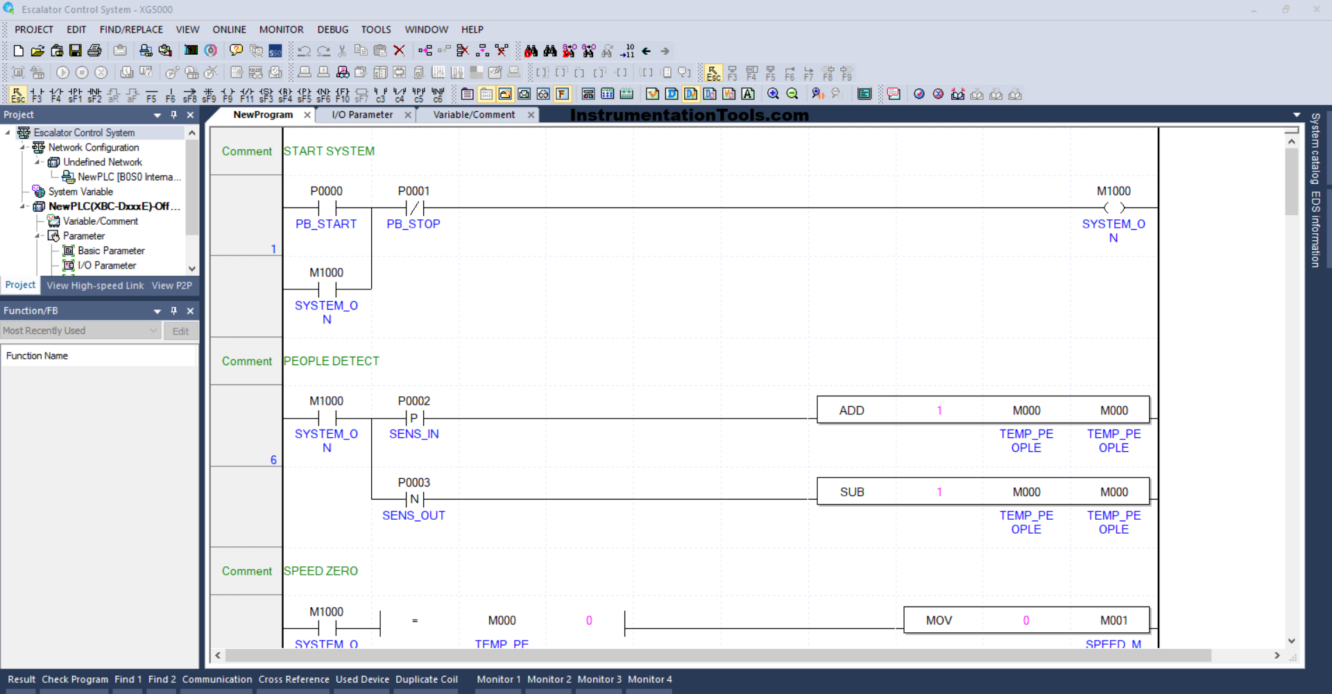
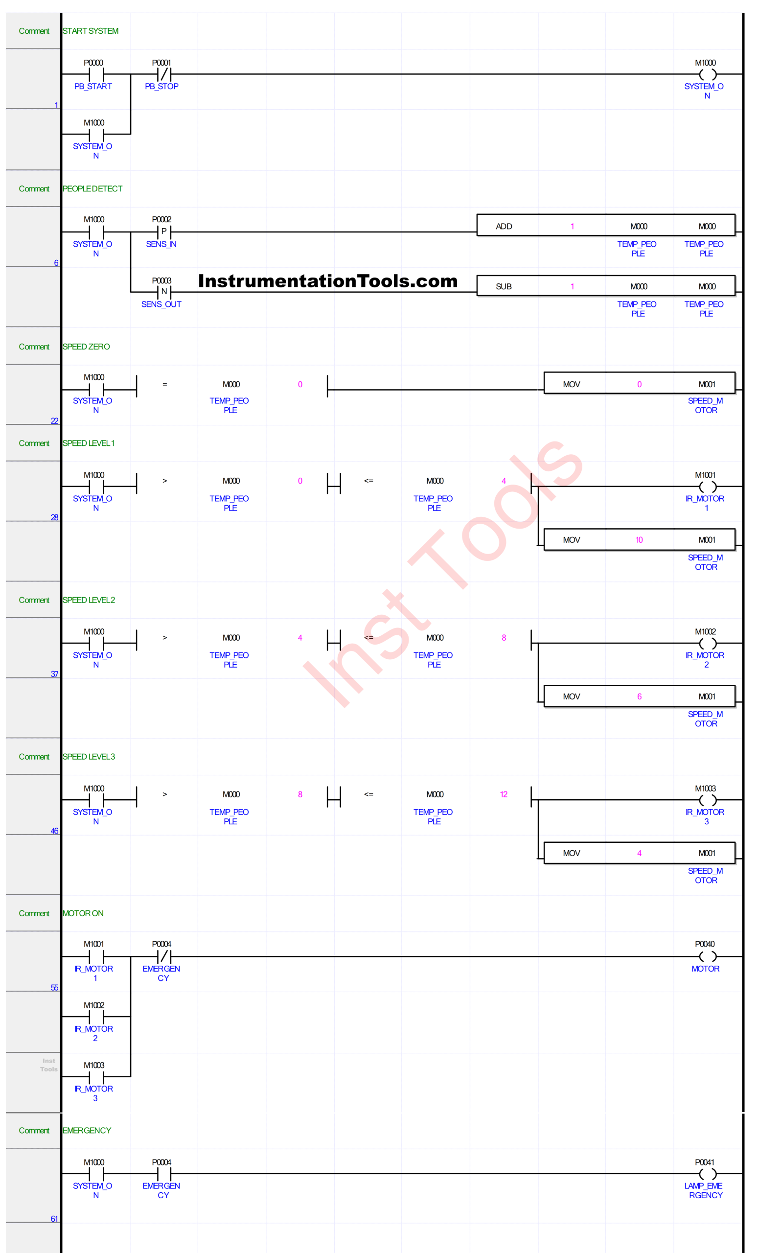
RUNG 1 (START SYSTEM)
In this Rung, when the PB_START (P0000) button is Pressed, the memory bit SYSTEM_ON (M1000) will be in the HIGH state. Because it uses Latching, the bit will remain in the HIGH state even though the PB_START (P0000) button has been Released.
The memory bit SYSTEM_ON (M1000) will return to the LOW state if the PB_STOP (P0001) button has been Pressed.
RUNG 6 (PEOPLE DETECT)
In this Rung, if the NO contact of the memory bit SYSTEM_ON (M1000) and the SENS_IN (P0002) sensor is in the HIGH state, then the value in the memory word TEMP_PEOPLE (M000) will increase (+1). Because it uses the ADD instruction.
And, if the NO contact of the memory bit SYSTEM_ON (M1000) and the SENS_OUT (P0003) sensor is in the HIGH state then the value in the memory word TEMP_PEOPLE (M000) will decrease (-1). Because it uses the SUB instruction.
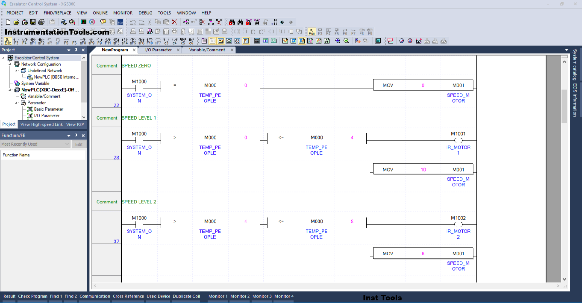
RUNG 22 (SPEED ZERO)
In this Rung, if the NO contact of the memory bit SYSTEM_ON (M1000) in the HIGH state and the value in the memory word TEMP_PEOPLE (M000) is Equal To zero “0”, then the memory word SPEED_MOTOR (M001) will become zero “0”, because the MOV instruction moves the zero value “0” to the memory word SPEED_MOTOR (M001).
RUNG 28 (SPEED LEVEL 1)
In this Rung, if contact NO of the memory bit SYSTEM_ON (M1000) in the HIGH state and the value in the memory word TEMP_PEOPLE (M000) is Greater Than “0” and Less Than or Equal To “4”, then the memory bit IR_MOTOR1 (M1001) will be in the HIGH state and the value in the memory word SPEED_MOTOR (M001) will be the value “10”.
The MOV instruction moves the value “10” to the memory word SPEED_MOTOR (M001).
RUNG 37 (SPEED LEVEL 2)
In this Rung, if contact NO of the memory bit SYSTEM_ON (M1000) in the HIGH state and the value in the memory word TEMP_PEOPLE (M000) is Greater Than “4” and Less Than or Equal To “8”, then the memory bit IR_MOTOR2 (M1002) will be in the HIGH state and the value in the memory word SPEED_MOTOR (M001) will be the value “6”.
The MOV instruction moves the value “6” to the memory word SPEED_MOTOR (M001).
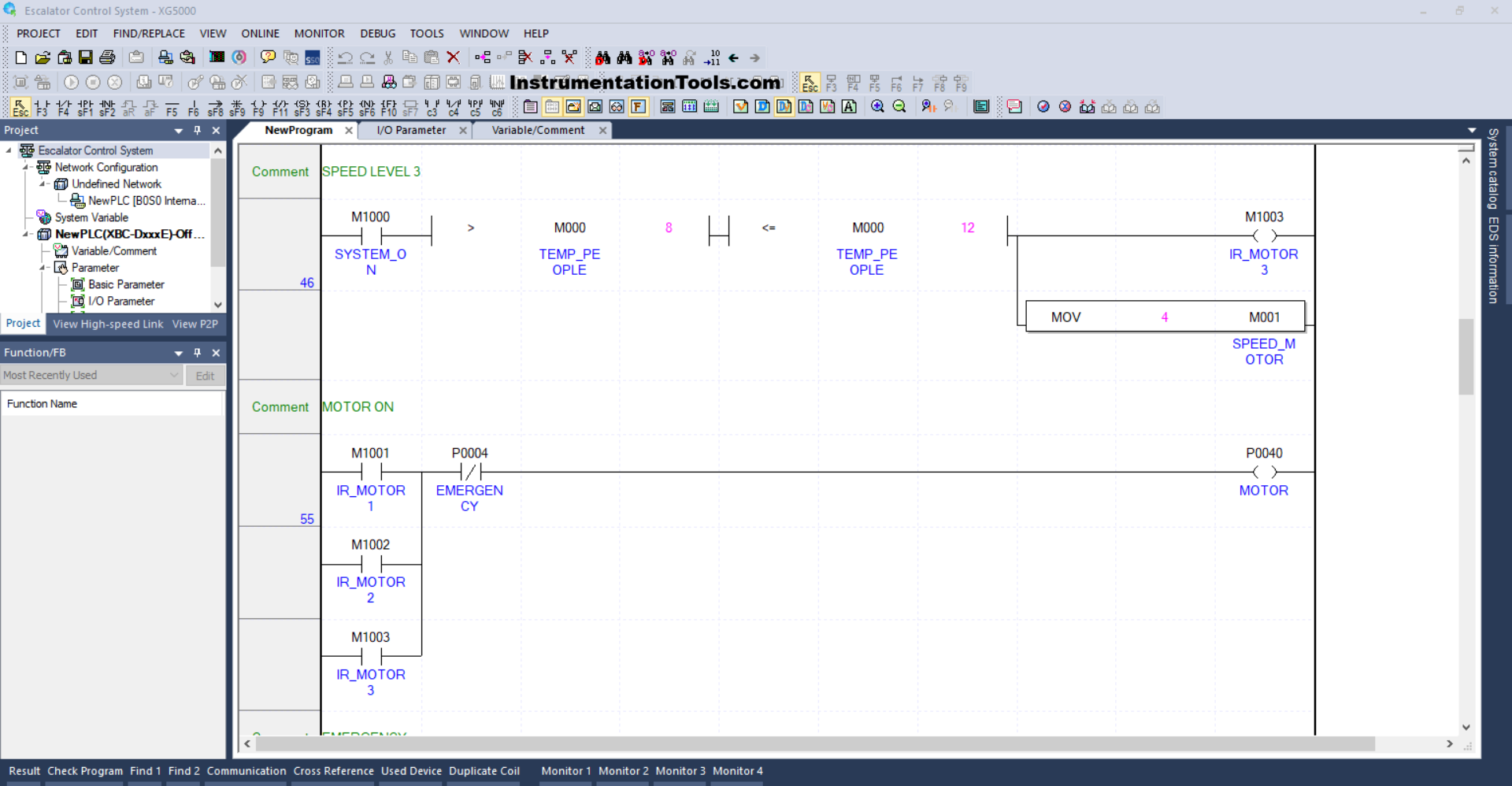
RUNG 46 (SPEED LEVEL 3)
In this Rung, when the NO contact of the memory bit SYSTEM_ON (M1000) in the HIGH state and the value in the memory word TEMP_PEOPLE (M000) is Greater Than “8” and Less Than or Equal To “12”, then the memory bit IR_MOTOR3 (M1003) will be in the HIGH state and the value in the memory word SPEED_MOTOR (M001) will be the value “4”.
The MOV instruction moves the value “4” to the memory word SPEED_MOTOR (M001).
RUNG 55 (MOTOR ON)
In this rung, if the NO contact of any of the memory bits IR_MOTOR1 (M1001), IR_MOTOR2 (M1002), or IR_MOTOR3 (M1003) is in a HIGH state, then the output MOTOR (P0040) will turn ON.
And when the EMERGENCY button (P0004) is Pressed, the output MOTOR (P0040) will turn OFF.
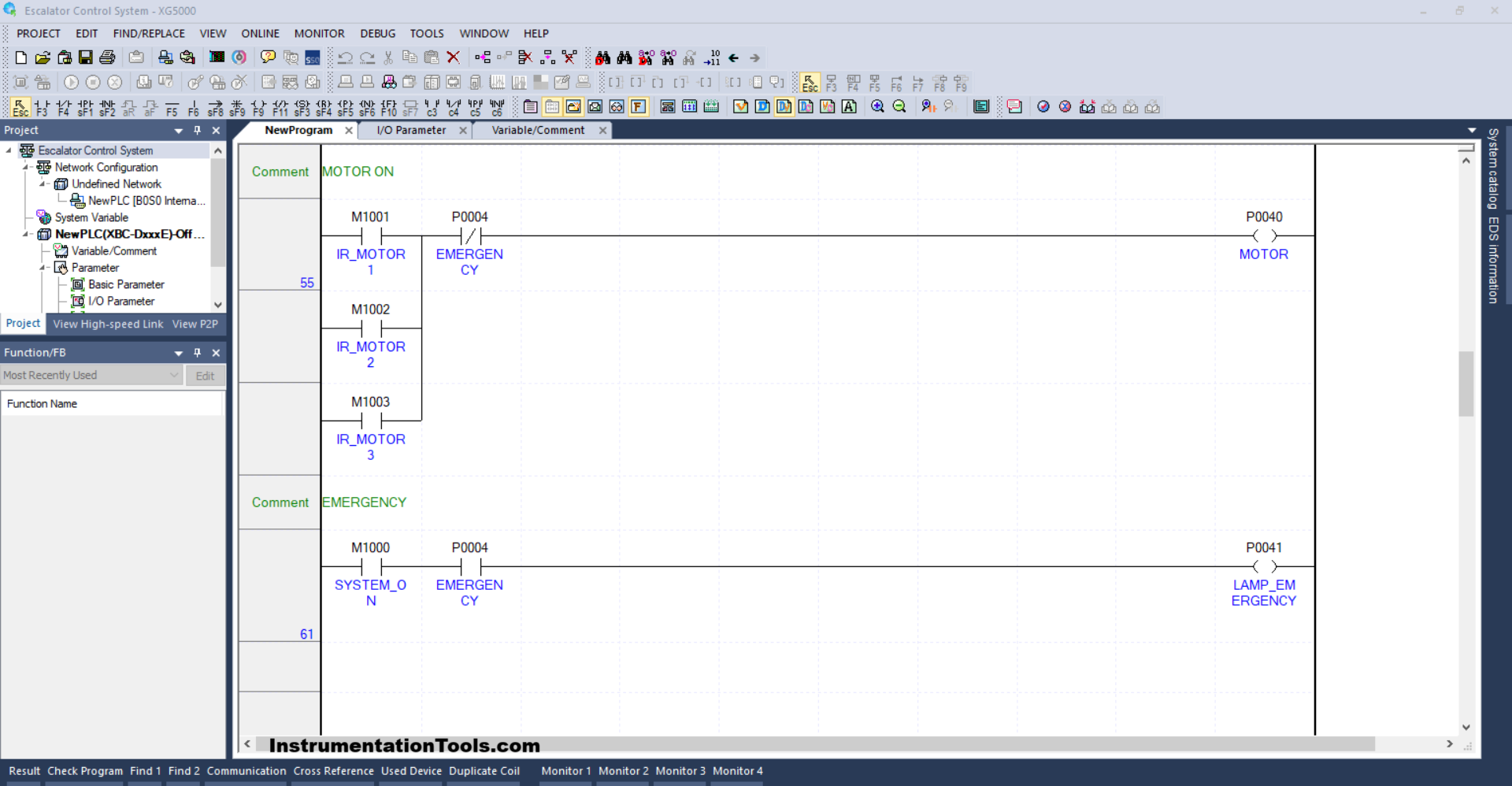
RUNG 61 (EMERGENCY)
In this Rung, when the EMERGENCY (P0004) button is Pressed, the LAMP_EMERGENCY (P0041) output will be ON.
Read Next:
- PLC Program for Fruit Sorting by Weight and Color
- OB20 Time Delay Interrupt Organization Block
- PLC OB10 Time of Day Interrupt Organization Block
- Siemens Tia Optimized and Standard Data Block Access
- Difference between Motion Controller and PLC System


